Correction coefficient obtaining method and array receiving system

A technology of correction coefficients and acquisition methods, applied in receiver monitoring, radio wave measurement systems, instruments, etc., can solve problems such as correcting array channel errors, and achieve the effect of overcoming drift and performance deterioration

Active Publication Date: 2020-11-10
NANCHANG UNIV
View PDF3 Cites 0 Cited by
  • Summary
  • Abstract
  • Description
  • Claims
  • Application Information

AI Technical Summary

Problems solved by technology

[0006] Based on this, the purpose of the present invention is to provide a correction coefficient acquisition method and an array receiving system to solve various problems caused by using a special correction circuit to correct array channel errors

Method used


Image

  • Correction coefficient obtaining method and array receiving system
  • Correction coefficient obtaining method and array receiving system
  • Correction coefficient obtaining method and array receiving system

Examples


Embodiment 1

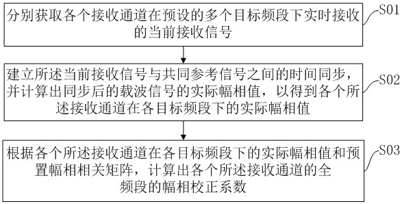
[0056] see figure 2 , which shows the correction coefficient acquisition method in the first embodiment of the present invention, which can be applied to an array receiving system, and the method is specifically:

[0057] Step S01, obtaining the current received signals received by each receiving channel in real time under a plurality of preset target frequency bands;

[0058] Step S02, establishing the time synchronization between the current received signal and the common reference signal, and calculating the actual amplitude and phase values ​​of the synchronized carrier signal, so as to obtain the actual amplitude and phase values ​​of each of the receiving channels in each target frequency band ;

[0059] Step S03 , calculating the amplitude and phase correction coefficients of each of the receiving channels in the entire frequency band according to the actual amplitude and phase values ​​of each of the receiving channels in each target frequency band and the preset amp...

Embodiment 2

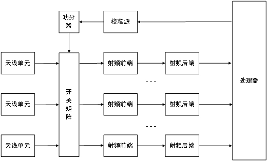
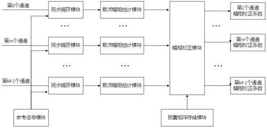
[0101] Another aspect of the present invention also provides an array receiving system, please refer to image 3 , shows the array receiving system in the second embodiment of the present invention, the array receiving system is a multi-channel full-band receiving system, and the array receiving system specifically includes:

[0102] A reference signal module, configured to generate a common reference signal required for time synchronization of each receiving channel;

[0103] A plurality of synchronous acquisition modules, each of the receiving channels is provided with a corresponding synchronous acquisition module, and the synchronous acquisition module is used to obtain the current received signal received by the corresponding receiving channel in real time under a plurality of preset target frequency bands , and establishing time synchronization between the current received signal and the common reference signal;

[0104] A plurality of carrier amplitude and phase estima...


PUM


Abstract

The invention provides a correction coefficient obtaining method and an array receiving system. The method comprises the following steps: respectively obtaining current receiving signals received by each receiving channel in real time under a plurality of preset target frequency bands; establishing time synchronization between the current receiving signal and the common reference signal, and calculating the actual amplitude-phase value of the synchronized carrier signal to obtain the actual amplitude-phase value of each receiving channel under each target frequency band; and calculating the full-band amplitude-phase correction coefficient of each receiving channel according to the actual amplitude-phase value of each receiving channel under each target frequency band and a preset amplitude-phase correlation matrix. According to the invention, the common reference signal is used as a reference and is combined with the external radiation signal, the actual amplitude-phase values of eachreceiving channel in a plurality of preset frequency bands are calculated in real time, and the actual amplitude-phase values are compared with the preset amplitude-phase correlation matrix, so that the multi-channel full-band correction coefficient of the system is calculated in real time. Drifting and performance deterioration of the system along with time are avoided, and design of a special receiving correction circuit is avoided.

Description

technical field [0001] The invention relates to the technical field of wireless information systems, in particular to a correction coefficient acquisition method and an array receiving system. Background technique [0002] In wireless communication (for example, 5G, 4G, tactical wireless communication, satellite communication), radar (phased array radar, multistatic radar, airborne radar, shipborne radar, spaceborne radar, etc.), passive detection, external source detection In the receiving system of modern electronic equipment, such as, the ultra-large-scale array receiving system is configured. For example, the array size of the receiving subsystem of Massive MIMO, a representative technology of 5G, can reach 64 channels; the array size of the receiving subsystem of phased array radar and phased array passive detection system can reach 1,000-100,000 receiving channels; The array size of the exogenous detection system is generally 5-17 channels. The receiving subsystem ad...

Claims


Application Information

Patent Timeline
Patent Type & Authority Applications(China)
IPC IPC(8): G01S7/40H04B17/21
CPCG01S7/40G01S7/4021H04B17/21Y02D30/70
Inventor 王正海王玉皞周辉林王早
Owner NANCHANG UNIV
Why Eureka
Try Eureka