Fluorescence response follow-up pinhole microscopic confocal measuring device

A technology of follow-up pinholes and measuring devices, applied in measuring devices, optical devices, fluorescence/phosphorescence, etc., can solve the problems of limited stray light suppression ability, inaccurate and difficult calculation of illuminated area, and achieve stray light suppression ability Strong, overcome pinhole drift, high accuracy effect

Active Publication Date: 2014-12-24
HARBIN INST OF TECH
View PDF4 Cites 0 Cited by
  • Summary
  • Abstract
  • Description
  • Claims
  • Application Information

AI Technical Summary

Problems solved by technology

[0005] The purpose of the present invention is to solve the problems caused by the introduction of the pinhole in the optical fiber confocal measurement and the traditional confocal measurement technology, which leads to the drift of the pinhole in the measurement process, the drift of the scanning focus spot, and the inaccurate calculation of the illuminated area in the virtual pinhole detection technology. In order to suppress the problem of limited ability and further reduce the difficulty of system pinhole installation and adjustment, a fluorescence response tracking pinhole microscopic confocal measurement device is provided, which utilizes the nonlinear optical characteristics of the fluorescent plate two-photon fluorescence response tracking pinhole effect Realize the role of virtual pinholes in focal microscopy, so that the pinholes of confocal microscopy technology have an adaptive adjustment function, overcome the deficiencies of pinhole drift in traditional confocal and focus spot drift during scanning, and replace actual pinholes with fluorescent plates or Single-mode optical fiber, introduces pinhole adjustment freedom, avoids adjustment difficulties, and has the characteristics of strong stray light suppression ability

Method used


Image

  • Fluorescence response follow-up pinhole microscopic confocal measuring device

Examples


Embodiment Construction

[0016] Embodiments of the present invention will be described in detail below in conjunction with the accompanying drawings.

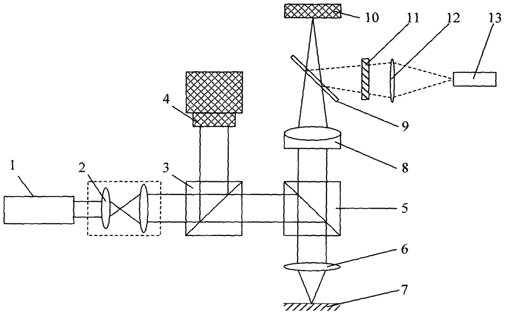
[0017] Fluorescence response follower pinhole micro confocal measurement device includes pulse laser 1, collimator beam expander 2, first beam splitter 3, optical power meter 4, second beam splitter 5, focusing objective lens 6, three-dimensional micro-displacement stage 7 , a telephoto doublet lens 8 and a dichroic mirror 9; wherein, a collimating beam expander 2, a first beam splitter 3 and a second beam splitter 5 are sequentially arranged on the direct optical path of the pulse laser 1, and the optical power meter 4 is configured on On the reflected light path of the first beam splitter 3, the focusing objective lens 6 and the three-dimensional micro-displacement stage 7 are sequentially arranged on the reflected light path of the second beam splitter 5, and the telephoto doublet lens 8 and the dichroic mirror 9 are sequentially arranged on the seco...


PUM


Abstract

The invention discloses a fluorescence response follow-up pinhole microscopic confocal measuring device and belongs to an optical micro measurement technology. A collimating beam expander, a first beam splitter and a second beam splitter are configured on a direct light path of a pulse laser; an optical power meter is arranged on the reflecting light path of the first beam splitter; a focusing object lens and a three-dimensional micro displacement objective table are arranged on a reflecting light path of the second beam splitter; a long-focus cemented doublet lens and a dichroscope are arranged on a transmitting light path of the second beam splitter; a two-photon fluorescence excitation reflector is arranged on the transmitting light path of the second beam splitter; and a narrow-band filter, a collecting objective lens and a high-gain photoelectric detector are arranged on a reflecting light path of the dichroscope. The device is provided with a pinhole which can adaptively adjust the degree of freedom, the problems of pinhole drift and scanning light spot drift in the measuring process are solved, and the device has the characteristics of high stray light suppression capacity, sensitive response and high accuracy.

Description

technical field [0001] The invention belongs to optical microscopic measurement technology, and mainly relates to an ultra-precise measuring instrument for three-dimensional microstructure, microstep, microgroove line width, depth and surface shape measurement in microstructured optical elements, microstructured mechanical elements, and integrated circuit elements. Non-contact measuring device. Background technique [0002] Confocal scanning measurement is one of the important technical means to measure three-dimensional microstructure, micro-step, micro-groove line width, depth and surface shape in the fields of micro-optics, micro-mechanics and micro-electronics. Its concept was first proposed by M.Minsky in 1957 and applied for a patent in 1961. The original intention of M.Minsky's design is to use point illumination and add a pinhole in front of the detector to suppress the stray light generated by ordinary optical microscopes when detecting samples. In the late 1970s,...

Claims


Application Information

Patent Timeline
Patent Type & Authority Patents(China)
IPC IPC(8): G01B11/00G01B11/02G01B11/22G01B11/24G01N21/64
Inventor 刘俭谭久彬王宇航
Owner HARBIN INST OF TECH
Why Eureka
Try Eureka