Capacitive circuit breaker topology suitable for high-voltage DC power grid

A high-voltage DC power grid and circuit breaker technology, which is applied in the direction of circuit devices, emergency protection circuit devices, electrical components, etc., can solve the problems of insufficient rapidity, high cost, and lack of reclosing ability, so as to enhance engineering feasibility and save The effect of low cost and low cost

Inactive Publication Date: 2020-11-10
NORTH CHINA ELECTRIC POWER UNIV (BAODING)
View PDF6 Cites 0 Cited by
  • Summary
  • Abstract
  • Description
  • Claims
  • Application Information

AI Technical Summary

Problems solved by technology

[0004] The purpose of the present invention is to overcome the shortcomings of current high-voltage DC circuit breakers, such as lack of rapidity, high cost, and lack of reclosing capability

Method used


Image

  • Capacitive circuit breaker topology suitable for high-voltage DC power grid
  • Capacitive circuit breaker topology suitable for high-voltage DC power grid
  • Capacitive circuit breaker topology suitable for high-voltage DC power grid

Examples


Embodiment Construction

[0023] The technical solutions in the embodiments of the present application will be clearly and completely described below in conjunction with the drawings in the embodiments of the present application.

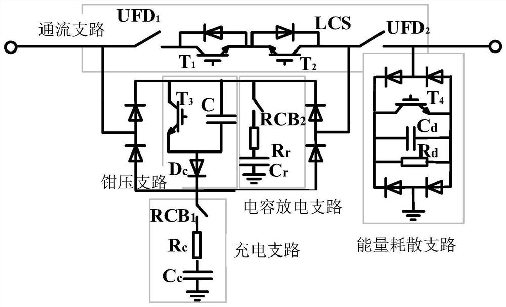
[0024] Capacitive circuit breaker topology such as figure 1 As shown, including the flow branch, charging branch, clamping branch, energy dissipation branch and capacitor discharge branch. The flow branch includes a load transfer switch and an ultra-fast mechanical switch UFD 1 、UFD 2 . In steady state, the normal working current flows; in case of fault, the fault current is transferred to the clamping branch. The clamping branch is the core branch of the topology, including the clamping capacitor C and the IGBT switch T 3 , Diode Dc. The clamping capacitor is connected to the fault circuit to absorb the fault energy when the fault occurs, and uses the high voltage charged by itself to "top" with the DC output voltage of the converter station, thereby clamping the volta...


PUM


Abstract

The invention relates to a capacitive circuit breaker topology suitable for a high-voltage DC power grid, and belongs to the technical field of multi-terminal DC and DC power grids. The capacitive circuit breaker topology comprises a through-current branch, a charging branch, a clamping branch, an energy dissipation branch and a capacitor discharging branch. A small-capacitance capacitor is connected to a fault loop to remove faults; a lightning arrester does not need to be used, and certain engineering value is achieved. The topology also has reclosing capability adapting to different fault conditions, and the reliability and the safety of the DC power grid can be improved.

Description

technical field [0001] The invention relates to a capacitive circuit breaker topology suitable for a high-voltage direct current power grid, belonging to the field of multi-terminal direct current and high-voltage direct current power grids. Background technique [0002] With the depletion of fossil resources worldwide, the development of renewable energy is unstoppable, and the flexible DC power grid is also developing rapidly. At present, the Zhangbei ±500kV four-terminal flexible DC power grid demonstration project under construction will realize the power supply of wind power to megacities through the DC power grid for the first time in the world. Compared with the traditional AC system, the DC grid composed of power electronic equipment is a "low inertia, low impedance" system, and the response time constant is at least 2 orders of magnitude smaller than that of the AC grid. When a serious fault occurs in the DC line, the converter and various energy storage elements o...

Claims


Application Information

Patent Timeline
IPC IPC(8): H02H7/26H02H3/06
CPCH02H7/268H02H3/066
Inventor 许建中武董一
Owner NORTH CHINA ELECTRIC POWER UNIV (BAODING)
Why Eureka
Try Eureka