
Manufacturing method of rigid-flex printed circuit board and rigid-flex printed circuit board

A technology for rigid-flex boards and manufacturing methods, which is applied in the field of rigid-flex boards and can solve problems such as solder mask peeling off, solder mask tearing, and inability to silk screen

Pending Publication Date: 2020-11-10
SHENZHEN SHIRUITAI TECH
View PDF0 Cites 1 Cited by
  • Summary
  • Abstract
  • Description
  • Claims
  • Application Information

AI Technical Summary

Problems solved by technology

[0003] For the rigid-flex board with partial solder mask on the flexible board, when the rigid board and the flexible board are pressed together, and then the flexible board area is opened and manufactured, the surface of the rigid board and the flexible board will be firm due to the pressing Therefore, it is easy to tear the solder mask layer when opening the cover, resulting in problems such as the solder mask layer falling off. If the silk screen of the solder mask layer is made after the rigid-flexible bonded board is produced, it will be due to the rigid-flexible bonded surface of the board. The boards are not on the same plane, resulting in problems such as oil leakage, misalignment, and even failure of silk screen printing
[0004] Therefore, it is necessary to design and develop a new method of opening the cover for the rigid-flex board with a partial solder mask on the flexible board, so as to avoid the problem of tearing the solder mask on the flexible board when the cover is opened.

Method used


Image

  • Manufacturing method of rigid-flex printed circuit board and rigid-flex printed circuit board
  • Manufacturing method of rigid-flex printed circuit board and rigid-flex printed circuit board
  • Manufacturing method of rigid-flex printed circuit board and rigid-flex printed circuit board

Examples


Embodiment Construction

[0039] The specific embodiments of the present invention will be further described below in conjunction with the drawings. It should be noted here that the description of these embodiments is used to help understand the present invention, but does not constitute a limitation to the present invention. In addition, the technical features involved in the various embodiments of the present invention described below can be combined with each other as long as they do not conflict with each other.

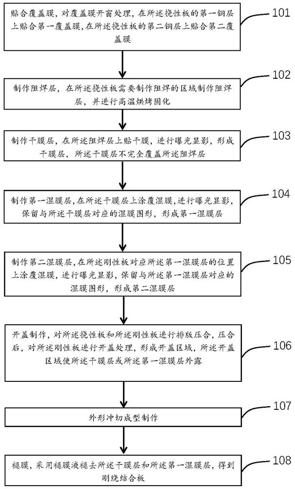
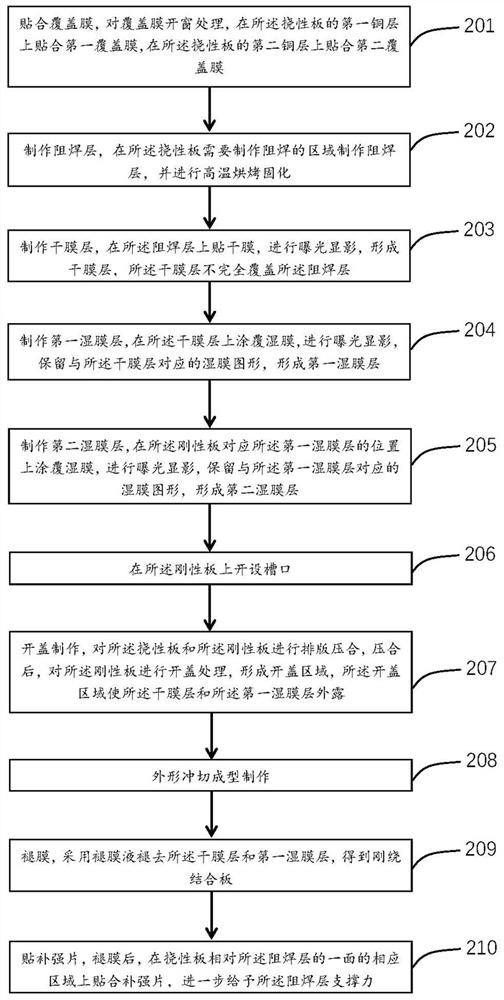
[0040] The present invention provides a method for manufacturing a rigid-flex board. At least one flexible board and at least two rigid boards are pressed together. Please refer to figure 1 , figure 1 It is a flowchart of a method for manufacturing a rigid-flex board according to an embodiment of the present invention. The manufacturing method includes the following steps:

[0041] Step 101: Laminate the cover film, open the window of the cover film, paste the first cover film on the first cop...


PUM


Abstract

The invention discloses a manufacturing method of a rigid-flexible printed circuit board. The method comprises the following steps of manufacturing a solder mask layer in an area of a flexible printedcircuit board where solder mask needs to be manufactured, baking at high temperature, pasting a dry film on the solder mask layer, exposing and developing to form a dry film layer, coating a wet filmon the dry film layer, exposing and developing, and reserving a wet film pattern corresponding to the dry film layer to form a first wet film layer; coating a wet film at the position, correspondingto the first wet film layer, of a rigid board, exposing and developing, reserving a wet film pattern corresponding to the first wet film layer, forming a second wet film layer, typesetting and laminating a flexible board and the rigid board, uncovering the rigid board after laminating to form an uncovering area, and exposing the dry film layer or the first wet film layer in the uncovering area; and removing the auxiliary area, and removing the dry film layer or the dry film layer and the first wet film layer by adopting a film removing solution to obtain the rigid-flexible printed circuit board. According to the manufacturing method of the rigid-flexible printed circuit board, the quality of the rigid-flexible printed circuit board can be effectively improved, and the problems that the rigid-flexible printed circuit board is scrapped in the uncovering process and the like are solved.

Description

Technical field [0001] The present invention relates to the manufacturing field of rigid-flex board, in particular to a method for manufacturing a rigid-flex board and a rigid-flex board. Background technique [0002] Rigid-Flex PCB is a printed circuit board in which a flexible board and a rigid board are combined with each other through the distribution of layers. The rigid-flex board has changed the traditional planar design concept and expanded to a three-dimensional three-dimensional space concept. While bringing great convenience to product design and application, it also increases the difficulty of manufacturing. [0003] For the flexible board, there is a rigid-flex board with a partial solder mask. When the rigid board and the flexible board are pressed together, and then the flexible board area is opened, the surface of the rigid board and the flexible board is firm due to the pressing Bonding, so it is easy to tear the solder mask when opening the cover, causing problem...

Claims


Application Information

Patent Timeline
IPC IPC(8): H05K3/46H05K3/36H05K3/22
CPCH05K3/361H05K3/4611H05K3/4691H05K3/22H05K2201/2009
Inventor 李永永王文剑肖华
Owner SHENZHEN SHIRUITAI TECH
Learn More