
A kind of dipping equipment for iron core transformer

A technology of iron core transformer and dipping paint, applied in the field of transformer iron core, can solve the problems of heat loss, damage to the surface paint layer of iron core, inability to impregnate the insulating paint, etc., to achieve the effect of increasing efficiency, uniform coverage and ensuring reliability

Active Publication Date: 2021-11-19
WUHU JINNIU ELECTRIC
View PDF9 Cites 0 Cited by
  • Summary
  • Abstract
  • Description
  • Claims
  • Application Information

AI Technical Summary

Problems solved by technology

[0003] In the prior art, the dipping and drying processes usually need to be operated separately, that is, after the dipping is completed, the iron core needs to be transported to the drying furnace for drying. This method not only increases the manpower for iron core handling, but also It is very easy to damage the paint layer on the surface of the iron core, resulting in uneven paint surface after drying, and the heat obtained by the iron core during the process of dipping paint is lost during the transportation process. When entering the drying process, it needs to be reheated and baked from normal temperature. Cause energy waste, so that the work efficiency is not high. At the same time, the existing paint dipping equipment is relatively cumbersome to put in and take out the iron core, and the efficiency is low. , on the contact surface between the fixture and the iron core, it is inevitable that there will be places where the insulating varnish cannot be impregnated, and it will also cause damage to the insulation performance of the iron core.

Method used


Image

  • A kind of dipping equipment for iron core transformer
  • A kind of dipping equipment for iron core transformer
  • A kind of dipping equipment for iron core transformer

Examples


Embodiment Construction

[0040] The technical solutions in the embodiments of the present invention will be clearly and completely described below in conjunction with the embodiments of the present invention. Apparently, the described embodiments are only some of the embodiments of the present invention, not all of them. Based on the embodiments of the present invention, all other embodiments obtained by persons of ordinary skill in the art without creative efforts fall within the protection scope of the present invention.

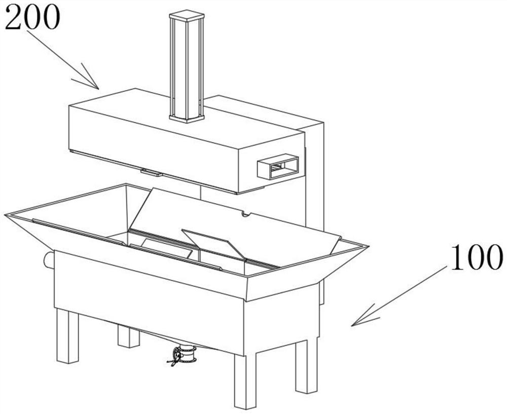
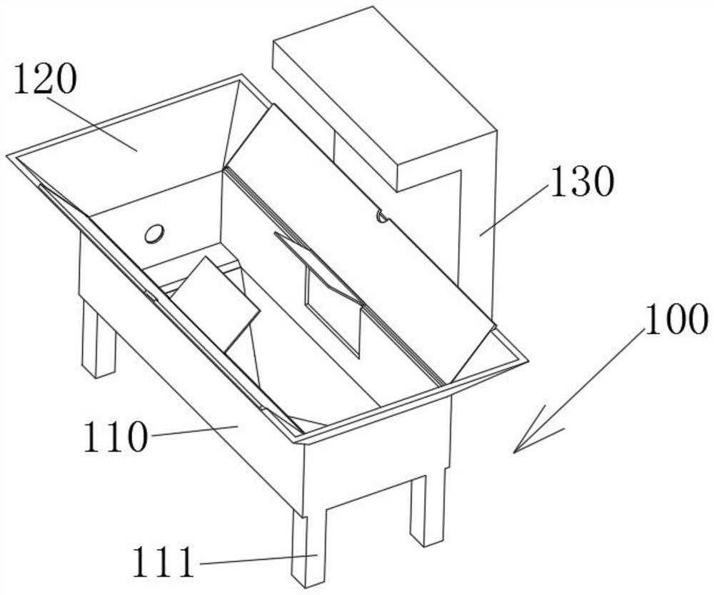
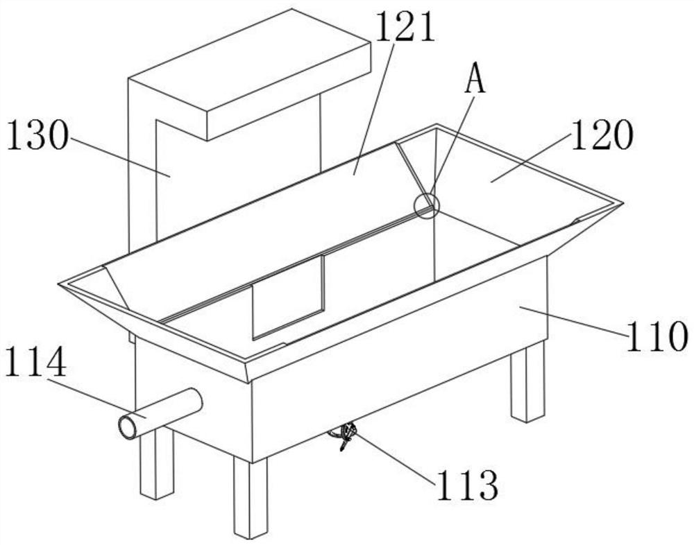
[0041] see Figure 1-20 As shown, a paint impregnating equipment for iron core transformers includes a paint impregnating module 100 and a drying module 200. The paint impregnating module 100 includes a housing 110 and a deflector 120. The four corners of the bottom surface of the housing 110 are all A support leg 111 is fixedly connected, one end of a liquid outlet pipe 112 is fixedly connected to the middle part of the bottom end of the housing 110, and a valve 113 is fixedly sl...


PUM


Abstract

The invention relates to the technical field of transformer iron cores, in particular to a paint impregnating equipment for iron core transformers, comprising a paint impregnating module and a drying module, the paint impregnating module includes a shell and a guide table, and the bottom surface of the shell is The four end corners of the housing are fixedly connected with outriggers, the middle part of the bottom end of the housing is fixedly connected with one end of the liquid outlet pipe, the other end of the liquid outlet pipe is sleeved and fixed with a valve, and a short end of the housing is The middle part of the side wall is fixedly connected with a vacuum conduit. In the present invention, slide rails are fixedly connected to both sides of the bottom surface of the drying box, and an airtight plate is slidably connected between the two slide rails, so that when the ejector rod drives the placement plate to rise and insert the placement plate into the drying box At the same time, the drying box is closed by sliding the airtight plate. On the one hand, the drying box is sealed to increase the drying efficiency; Spread to the insulating varnish in the lower casing, ensuring the reliability of the unused insulating varnish.

Description

technical field [0001] The invention relates to the technical field of transformer iron cores, in particular to a paint dipping equipment for iron core transformers. Background technique [0002] The iron core plays the role of converting magnetic energy into electrical energy and changing the voltage and current in the working engineering of the transformer. It is the core component of the transformer. The iron core is usually made of hot-rolled or cold-rolled steel with a high silicon content and an insulating varnish on the surface. Silicon steel sheets are stacked. In the production process, in order to ensure its insulation performance, the iron core needs to be soaked in insulating paint. After the paint is evenly infiltrated into the inner and outer rings of the iron core, the drying process is carried out. Vacuum impregnation is the most commonly used method of impregnation now; [0003] In the prior art, the dipping and drying processes usually need to be operated ...

Claims


Application Information

Patent Timeline
Patent Type & Authority Patents(China)
IPC IPC(8): B05C9/14B05C15/00B05C3/10B05C11/10B05C13/02
CPCB05C3/10B05C9/14B05C11/1039B05C13/02B05C15/00
Inventor 田奇旋
Owner WUHU JINNIU ELECTRIC
Learn More