Deburring and grinding device for brake disc

A technology for deburring and brake discs, which is applied in the direction of grinding drive devices, devices for fixing grinding wheels, grinding/polishing safety devices, etc. It can solve problems such as low efficiency and cumbersome procedures, reduce output energy consumption, and improve processing efficiency , the effect of quick positioning

Active Publication Date: 2020-11-13
LAIZHOU SANLI AUTO PARTS
View PDF5 Cites 3 Cited by
  • Summary
  • Abstract
  • Description
  • Claims
  • Application Information

AI Technical Summary

Problems solved by technology

[0003] Most of the existing brake discs adopt a double-piece design. When using traditional deburring and grinding devices to process the brake disc, it is often necessary to polish the surface to be treated and the mounting hole separately. The process is cumbersome and the efficiency is low.

Method used


Image

  • Deburring and grinding device for brake disc
  • Deburring and grinding device for brake disc
  • Deburring and grinding device for brake disc

Examples


Embodiment Construction

[0029] Example embodiments will now be described more fully with reference to the accompanying drawings. Example embodiments may, however, be embodied in many forms and should not be construed as limited to the examples set forth herein; Fully conveyed to those skilled in the art. The drawings are merely schematic illustrations of the present disclosure and are not necessarily drawn to scale. The same reference numerals in the drawings denote the same or similar parts, and thus repeated descriptions thereof will be omitted.

[0030] Furthermore, the described features, structures, or characteristics may be combined in any suitable manner in one or more example embodiments. In the following description, numerous specific details are provided in order to give a thorough understanding of example embodiments of the present disclosure. However, those skilled in the art will appreciate that the technical solutions of the present disclosure may be practiced without one or more of ...


PUM


Abstract

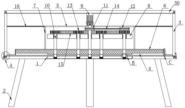
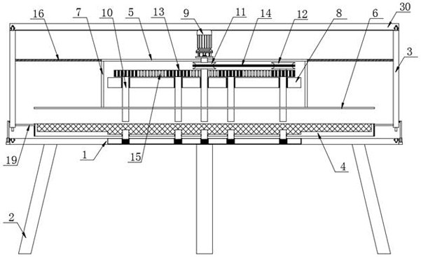
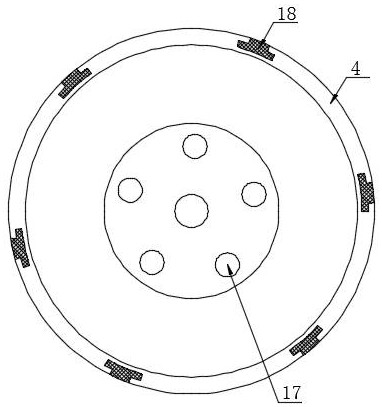
The invention discloses a deburring and grinding device for a brake disc, and particularly relates to the technical field of brake disc machining. The deburring and grinding device comprises a base plate and a cover plate which are arranged in parallel, wherein the cover plate is located at the top of the base plate, supporting legs are arranged at the bottom of the base plate, a sleeve is arranged between the base plate and the cover plate, a grinding mechanism is arranged inside the sleeve, annular inserting blocks are fixedly arranged in the middles of the top end surface and the bottom endsurface of the sleeve, and annular inserting grooves matched with the corresponding annular inserting blocks are formed in the edges of the sides, opposite to the cover plate, of the base plate. According to the deburring and grinding device, a hydraulic cylinder drives the sleeve to move upwards, then the to-be-treated surface of the brake disc makes contact with the grinding surface of a grinding disc, then the hydraulic cylinder drives a piston rod at the end part of the hydraulic cylinder to retract back till the annular inserting block at the bottom end of the sleeve is completely inserted into the annular inserting groove in the top of the base plate, and then a first disc can be driven by a servo motor to rotate to complete grinding of the to-be-ground surface of the brake disc andmounting holes.

Description

technical field [0001] The invention relates to the technical field of brake disc processing, and more specifically, the invention relates to a deburring and grinding device for brake discs. Background technique [0002] The brake disc is an important part of the car braking system. A good brake disc has stable braking, no noise, and no vibration. The brake disc is usually formed by stamping, so burrs are easy to appear on its surface or corners. These burrs Existence makes the surface of the brake disc rough and uneven, and when it is used in equipment, it often causes damage such as scratches to the equipment. Therefore, after the stamping of the brake disc is completed, the burrs on its surface need to be treated. [0003] Most of the existing brake discs adopt a double-piece design. When using traditional deburring and grinding devices to process the brake disc, it is often necessary to polish the surface to be treated and the mounting hole separately, which is cumberso...

Claims


Application Information

Patent Timeline
IPC IPC(8): B24B9/04B24B45/00B24B5/48B24B55/06B24B47/12B24B55/00
CPCB24B5/48B24B9/04B24B45/006B24B47/12B24B55/00B24B55/06
Inventor 王平王爱军彭志超王亚祥
Owner LAIZHOU SANLI AUTO PARTS
Why Eureka
Try Eureka