Full-automatic inspection robot chassis

An inspection robot, fully automatic technology, applied in the direction of instruments, motor vehicles, electric vehicles, etc., can solve problems such as falling and breaking equipment, difficulty in automatic charging of robots, and collision with cabinets

Pending Publication Date: 2020-11-13
佛山哨马智能装备科技有限公司
View PDF0 Cites 0 Cited by
  • Summary
  • Abstract
  • Description
  • Claims
  • Application Information

AI Technical Summary

Problems solved by technology

[0004] In order to solve the above technical problems, the purpose of the present invention is to provide a fully automatic inspection robot chassis, which can solve the problem that the inspection robot collides with the cabinet during autonomous inspection and falls and breaks the equipment when encountering steps, and can also solve the problem of the robot The difficulty of automatic charging, and the problem that the mecanum wheel falls off when the mecanum-driven inspection robot adopts ordinary couplings when moving forward, laterally moving or turning, can also realize the automatic navigation of the robot, The mechanism of the invention is simple in design, convenient in installation, reliable in operation and obvious in effect

Method used


Image

  • Full-automatic inspection robot chassis
  • Full-automatic inspection robot chassis
  • Full-automatic inspection robot chassis

Examples


Embodiment 1

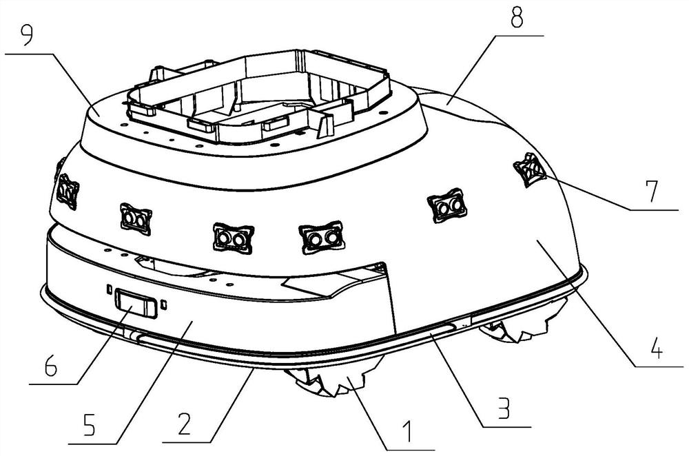
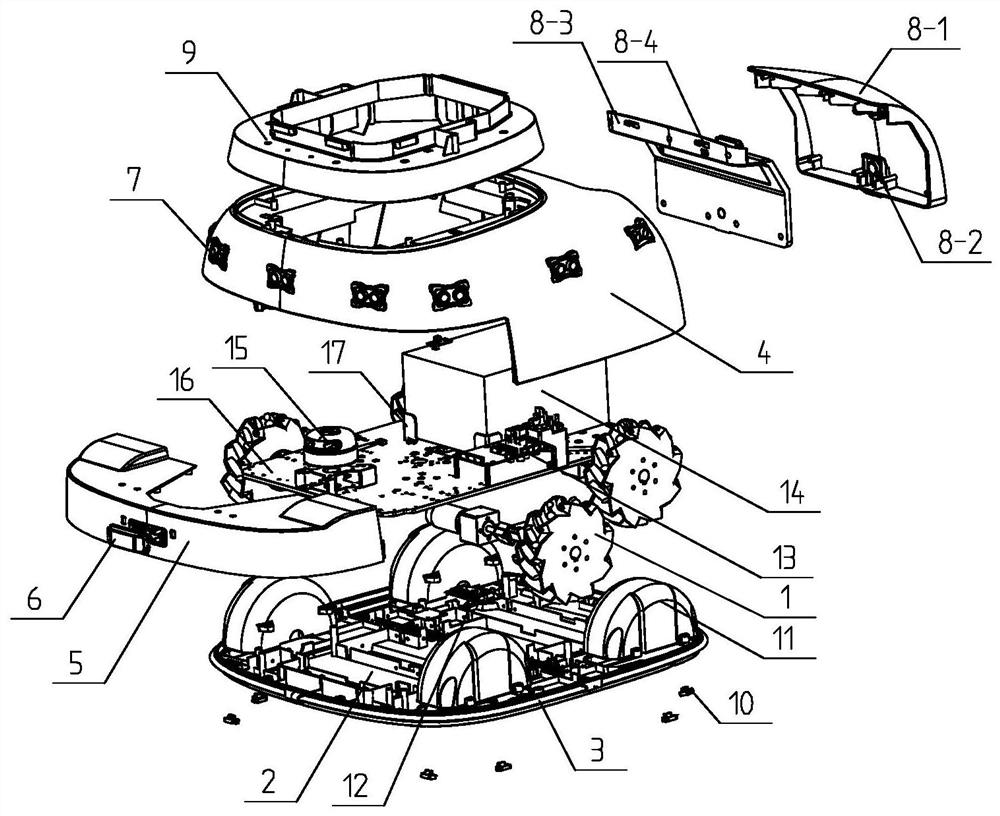
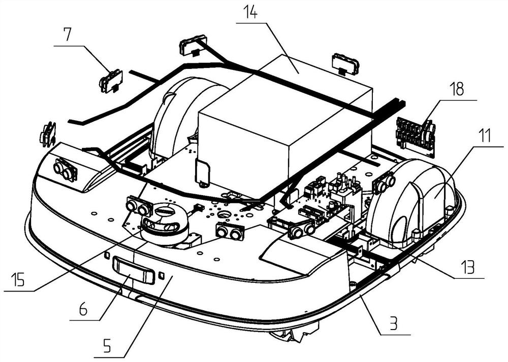
[0026] Refer to attached figure 1 to attach Figure 7 , a fully automatic inspection robot chassis, including drive wheel 1, chassis shield 2, anti-collision strip 3, chassis shell 4, front guard plate 5, infrared receiver 6, ultrasonic radar 7, battery back cover 8, upper installation Shell 9, drop trigger 10, road wheel shield 11, drop control board 12, drive board 13, power battery 14, laser radar 15, drive motor mounting board 16, battery positioning seat 17, anti-collision strip drive board 18, temperature Humidity sensor 19 and charging contact 20, the drive wheel 1 is fixed on the four corners of the drive motor mounting plate 16, the chassis shield 2 is fixed on the drive motor mounting plate 16 by fastening bolts, and the anti-collision strip is 3 weeks It is installed on the chassis shield 2 in the opposite direction, and is used for the perception of obstacles encountered by the robot. The road wheel shield 11 is fixed on the chassis shield 2 by bolt locking, and t...

Embodiment 2

[0028]The difference between this embodiment and Embodiment 1 is that the drive wheel 1 includes a drive motor 1-1, a reducer 1-2, a shaft coupling 1-3, a bearing mounting seat 1-4, and a connecting flange 1- 5. The mecanum wheel 1-6 and the drive wheel connecting shaft 1-7 are characterized in that: the drive motor 1-1 is connected to the reducer 1-2, and the reducer 1-2 adopts a tight The solid screw is fixed on the drive motor mounting plate 16, and the shaft coupling 1-3 is used to connect the output shaft of the reducer 1-2 and the drive wheel connection shaft 1-7, so as to transmit the motor motion to the mecanum wheel 1-6, The bearing mount 1-4 is arranged on one side of the shaft coupling 1-3 for supporting the driving wheel connecting shaft 1-7, and the connecting flange 1-5 is arranged on the driving wheel connecting shaft 1-7 and the Mecanum wheel Between 1-6, wherein the driving wheel connecting shaft 1-7 is fixed on the inner surface of the connecting flange 1-5 b...

Embodiment 3

[0030] The difference between this embodiment and Embodiment 2 is that the output shaft of the reducer 1-2 is provided with a reducer output shaft key head 1-2-1 and a reducer output shaft keyway 1-2-2, and the above-mentioned reducer The selection range of the width of the key head 1-2-1 of the output shaft of the reducer is 5-10mm, and the height of the key head 1-2-1 of the output shaft of the reducer is 5mm.


PUM


Abstract

The invention relates to a moving chassis device of a full-automatic inspection robot, in particular to a chassis device of a mobile robot, which can provide accurate positioning, autonomous navigation and high reliability and has anti-falling, anti-collision, automatic navigation and autonomous charging functions, and the chassis device can be applied to an all-weather inspection robot for IDC machine room equipment and environment monitoring. The invention provides a chassis device for full-automatic obstacle avoidance and navigation of an inspection robot. The accidents that the inspectionrobot collides with a cabinet during autonomous inspection and falls off to damage equipment when encountering steps can be avoided; the problem that the robot is difficult to charge automatically canbe solved, the problem that Mecanum wheels fall off when the inspection robot driven by Mecanum moves forwards or transversely or makes a turn and the like through a common coupler is solved, automatic navigation of the robot can be achieved, and the chassis device is simple in design, convenient and fast to install, reliable in work and obvious in effect.

Description

technical field [0001] The invention relates to a mobile chassis device for a fully automatic inspection robot, in particular to a chassis device for a mobile robot that can provide precise positioning, high reliability, anti-drop, anti-collision, automatic navigation, and autonomous charging, and belongs to the mobile inspection robot. Check the field of robotics. Background technique [0002] With the rapid development of the Internet industry, the application of operation and maintenance centers and operation and maintenance servers is becoming more and more extensive. In order to ensure the normal operation of the servers in the computer room and to discover equipment defects or hidden dangers in a timely manner, it is often necessary for the operation and maintenance personnel of the computer room to check the equipment in the computer room regularly or irregularly, and to manually copy the instruments and meters, which is a heavy workload and Affected by factors such ...

Claims


Application Information

Patent Timeline
Patent Type & Authority Applications(China)
IPC IPC(8): B62D63/02B62D63/04B60R19/02B60K1/04B60L53/80G01D21/02G05D1/00G05D1/02
CPCB60K1/04B60R19/02B62D63/02B62D63/04B60L53/80G01D21/02G05D1/0005G05D1/0088G05D1/024G05D1/0242G05D1/0255G05D1/0257Y02T10/70Y02T10/7072
Inventor 李振徐飞代青平蒙达生杜晶晶秦俊鑫陆志
Owner 佛山哨马智能装备科技有限公司
Why Eureka
Try Eureka