Multi-specification bagging auxiliary device for chemical fertilizer
An auxiliary device, multi-specification technology, applied in the field of packaging, can solve problems affecting workers' health and other issues
- Summary
- Abstract
- Description
- Claims
- Application Information
AI Technical Summary
Problems solved by technology
Method used
Image
Examples
Embodiment 1
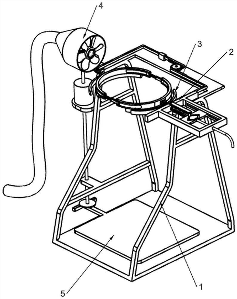
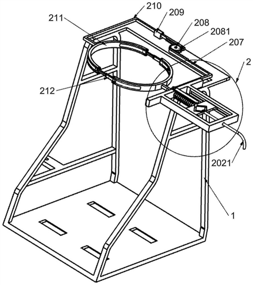
[0027] like Figure 1-Figure 5 As shown, a multi-specification bagging auxiliary device for chemical fertilizers includes a bracket 1, an adjustment mechanism 2 and a clamping mechanism 3. An adjustment mechanism 2 is connected to the upper right side of the bracket 1, which is used to adjust packaging bags of different sizes. The adjustment mechanism The left side of 2 is connected with a clamping mechanism 3, which is used for clamping the edge of the packaging bag to facilitate bagging.
[0028] The adjusting mechanism 2 includes a sliding frame 201, a moving frame 202, a pulling handle 2021, a pulling rod 203, a spring 1 204, a fixed round block 205, a movable frame 206, a rack 1 207, a rotating rod 1 208, a rotating gear 2081, a guide block 209. The second rack 210, the telescopic ring 211 and the movable rod 212, a sliding frame 201 is fixedly connected to the upper right side of the bracket 1, and the slots on the front and rear sides of the sliding frame 201 are slidab...
Embodiment 2
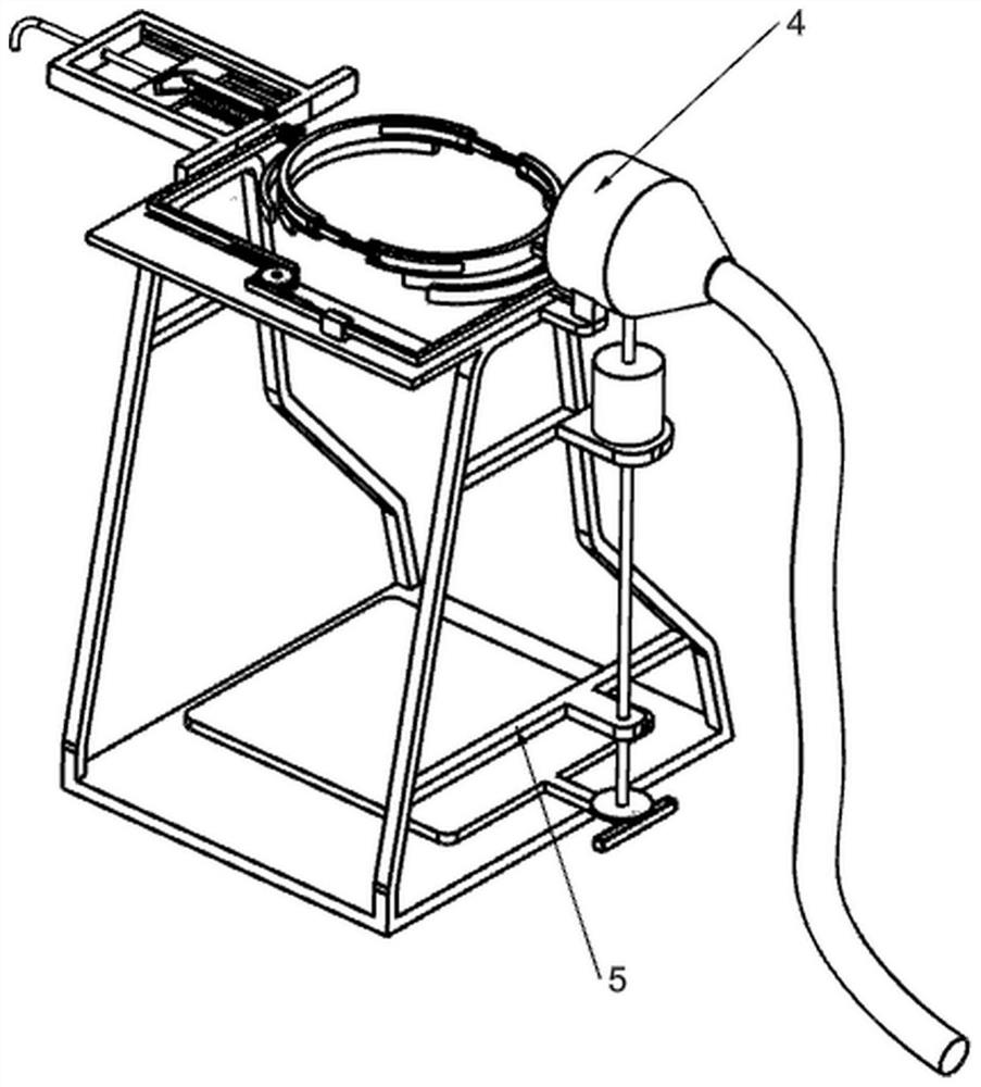
[0034] On the basis of Example 1, as Figure 6-Figure 8 As shown, it also includes a suction mechanism 4. The suction mechanism 4 includes a support plate 401, a motor 402, a power shaft 403, a mounting plate 404, a suction casing 405, a support seat 406, a rotating rod 407, and a bevel gear 408. and fan blade 409, a support plate 401 is fixedly installed on the upper left side of the bracket 1, a motor 402 is installed above the support plate 401, a power shaft 403 is connected to the output shaft of the motor 402, and a mounting plate is fixedly connected to the upper left side of the bracket 1 Plate 404, a suction casing 405 is fixedly connected to the front side of the mounting plate 404, and a support seat 406 is fixedly connected to the inner side of the suction casing 405. Actively connected, the right part of the support base 406 is rotatably connected with the second rotating rod 407, the end of the power shaft 403 away from the output shaft of the motor 402 and the l...
Embodiment 3
[0037] On the basis of Example 2, as Figure 9 As shown, it also includes a shaking mechanism 5. The shaking mechanism 5 includes a fixed frame 501, a rotating shaft 502, a rotating disk 503, a sliding block 504 and a moving plate 505. The left inner side of the bracket 1 is fixedly connected with a fixed frame 501, and a motor 402 The bottom output shaft of the motor 402 is connected with a rotating shaft 502. The rotating shaft 502 is rotatably connected with the support plate 401 and the fixing frame 501 through a bearing. The end of the rotating shaft 502 away from the output shaft of the motor 402 is fixedly installed with a rotating plate 503. A sliding block 504 is slidably connected to some notches, and a moving plate 505 is fixedly installed above the sliding block 504 .
[0038] During the bagging process, the bottom of the bag will be unevenly packed, which will affect the overall bagging. We can start the motor 402 to rotate forward, and the forward rotation of the...
PUM
 Abstract
Description
Claims
Application Information
 - R&D
- Intellectual Property
- Life Sciences
- Materials
- Tech Scout
- Unparalleled Data Quality
- Higher Quality Content
- 60% Fewer Hallucinations
Browse by: Latest US Patents, China's latest patents, Technical Efficacy Thesaurus, Application Domain, Technology Topic, Popular Technical Reports.
© 2025 PatSnap. All rights reserved.Legal|Privacy policy|Modern Slavery Act Transparency Statement|Sitemap|About US| Contact US: help@patsnap.com


