Composting pool

A composting pond and composting technology, applied in the field of composting ponds, can solve the problems of power consumption cost, large floor area, and single function of composting ponds, and achieve the effects of improving unloading efficiency, saving labor costs, and ensuring fermentation effects

Active Publication Date: 2020-11-13
肖金来
View PDF8 Cites 1 Cited by
  • Summary
  • Abstract
  • Description
  • Claims
  • Application Information

AI Technical Summary

Problems solved by technology

[0003] However, the existing compost pools are mainly divided into four categories during use: strip composting, static aeration composting, trough aerobic composting, and container composting. However, strip composting not only requires manual turning, but also occupies a large area. At the same time, static ventilation composting needs to use fans for ventilation, so it consumes a certain amount of electricity costs and reduces the practicability of the composting pool. Secondly, the existing composting pools have relatively simple functions, and cannot detect the temperature and humidity in the composting pool, and thus cannot make the fertilizer. Better fermentation will affect the fermentation effect of fertilizers and reduce the functionality of composting tanks. In addition, the existing composting tanks need to be manually unloaded during the unloading process, and manual unloading is not only a waste of time, but also wastes manpower and material resources, reducing The unloading efficiency of the compost pond, so there is an urgent need for a compost pond to solve the existing problems

Method used


Image

  • Composting pool
  • Composting pool
  • Composting pool

Examples


Embodiment Construction

[0036] The present invention will be further described below in conjunction with accompanying drawing:

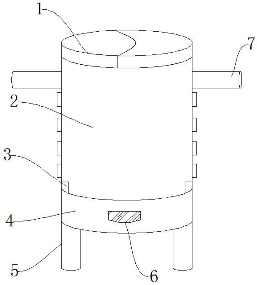
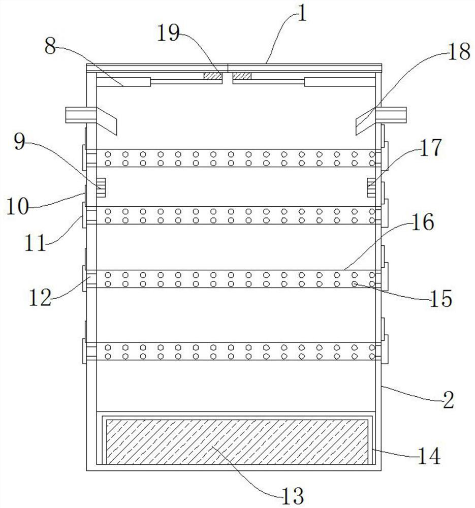
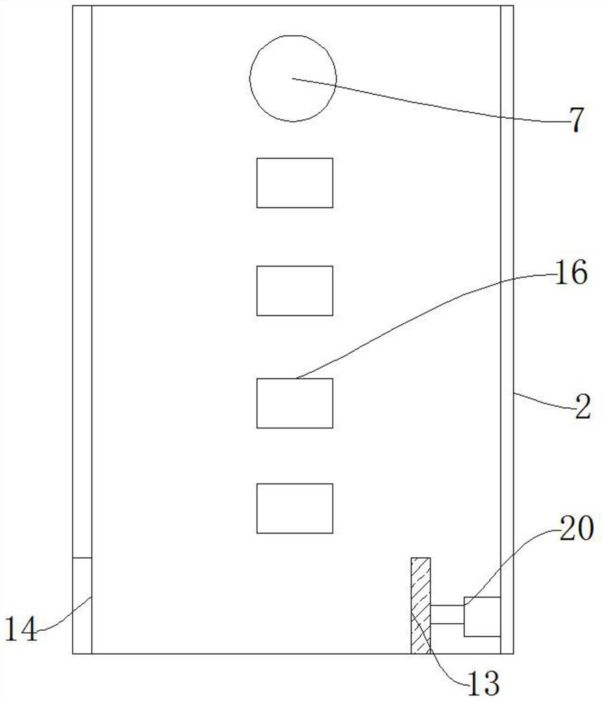
[0037] Such as Figure 1-Figure 4 As shown, a composting pond includes a silo 2, a silo cover 1, a support leg 5 and a composting pipe 16. An electric push rod 8 is provided on the upper end of the inner wall of the silo 2, and a connecting rod 8 is provided on one side of the electric push rod 8. Block 19, the upper end of the connecting block 19 is provided with the bin cover 1, the two side walls of the bin 2 are provided with a connecting water pipe 7, and one end of the connecting water pipe 7 is provided with a nozzle 18, and the inner wall of the bin 2 The composting pipe 16 is arranged between them, the composting pipe 16 is provided with a ventilation hole 15, the two ends of the composting pipe 16 are provided with a ventilation hole 12, and one side of the ventilation hole 12 is provided with a ventilation baffle 11, so One side of the ventilation baffle 11 is p...


PUM


Abstract

The invention discloses a composting pool which comprises a stock bin, a bin cover, supporting legs and a composting pipe, an electric push rod is arranged at the upper end of the inner wall of the stock bin, a connecting block is arranged on one side of the electric push rod, and the bin cover is arranged at the upper end of the connecting block. Beneficial effects are that: the stock bin, the composting pipe and the vent hole are arranged, the labor cost, the construction cost and the occupied area of the device can be saved, and the interior of the device can be ventilated without electrical equipment and mechanical equipment, organic matters in the device can be subjected to aerobic fermentation and the device practicability is improved; a temperature sensor and a humidity sensor are arranged, the temperature sensor can detect the temperature in the device in real time, the humidity sensor can detect the humidity in the device in real time, when the temperature or humidity in the device is not adaptive to the temperature and the humidity of organic matter fermentation, corresponding adjusting measures can be taken in time, the fermentation effect of organic matter is guaranteed, and the functionality of the device is improved.

Description

technical field [0001] The invention relates to the technical field of composting, in particular to a composting pond. Background technique [0002] Composting is a biochemical process that uses bacteria, actinomycetes, fungi and other microorganisms widely distributed in nature to promote the transformation of biodegradable organic matter into stable humus in a controlled manner under certain artificial conditions. During the fermentation process, during the composting process, organic carbon is respired and metabolized by microorganisms, thereby reducing the carbon-to-nitrogen ratio, and the heat generated can make the compost temperature reach above 70°C, which can kill germs, insect eggs and weed seeds, making it softer after accumulation And it is good for spreading. After being made into compost, it not only has no odor but also has the fragrance of soil. [0003] However, the existing compost pools are mainly divided into four categories during use: strip composting,...

Claims


Application Information

Patent Timeline
Patent Type & Authority Applications(China)
IPC IPC(8): C05F17/964C05F17/993C05F17/90
CPCC05F17/964C05F17/993C05F17/90Y02W30/40
Inventor 肖金来
Owner 肖金来
Why Eureka
Try Eureka