

Mortar spraying device with gradually-changed spraying direction
A spraying device and gradient technology, which is applied in the field of spraying direction gradient mortar spraying device to achieve the effect of preventing precipitation or condensation
- Summary
- Abstract
- Description
- Claims
- Application Information
AI Technical Summary
Problems solved by technology
Method used
Image

Examples
specific Embodiment approach 1
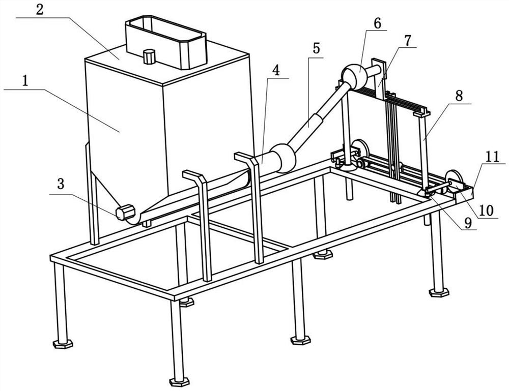
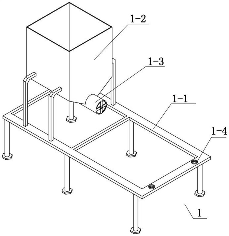
[0035] Combine below Figure 1-12Describe this embodiment, a spraying direction gradient type mortar spraying device, including a support frame assembly 1, a stirring assembly 2, a feeding assembly 3, a first connecting pipe 4, a second connecting pipe 5, a spraying pipe 6, a limit assembly 7, The lifting assembly 8, the intermittent transmission assembly 9, the transmission assembly 10 and the traverse assembly 11, the stirring assembly 2 is fixedly connected to the support frame assembly 1, the feeding assembly 3 is fixedly connected to the support frame assembly 1, and the first connecting pipe 4 is fixedly connected to the On the support frame assembly 1, the second connecting pipe 5 is hinged on the first connecting pipe 4, the spraying pipe 6 is hinged on the second connecting pipe 5, the limit assembly 7 is fixedly connected to the spraying pipe 6, and the lifting assembly 8 slides Connected to the support frame assembly 1, there are two intermittent transmission assemb...
specific Embodiment approach 2
[0038] Combine below Figure 1-12 To illustrate this embodiment, the traversing assembly 11 includes a traversing frame 11-1, a reciprocating motor 11-2, a pulley 11-3, a toothed belt 11-4, a reciprocating rod 11-5 and a motor output wheel 11-6 , the reciprocating motor 11-2 is fixedly connected to the traversing frame 11-1, and the two motor output wheels 11-6 are respectively fixedly connected to the front and rear sides of the traversing frame 11-1, and the two motor output wheels 11-6 are There are two pulleys 11-3 fixedly connected, the motor output pulley 11-6 at the front end is fixedly connected on the output shaft of the reciprocating motor 11-2, the two pulleys 11-3 are driven by the toothed belt 11-4, and the reciprocating rod 11-5 is fixedly connected on the toothed belt 11-4.
[0039] Start the reciprocating motor 11-2, the reciprocating motor 11-2 drives the motor output wheel 11-6 fixedly connected with it to rotate, the motor output wheel 11-6 at the front end...
specific Embodiment approach 3
[0041] Combine below Figure 1-12 To illustrate this embodiment, the transmission assembly 10 includes a transmission fixing plate 10-1, a transmission worm shaft 10-2 and a reduction gear 10-3. The transmission worm shaft 10-2 is rotatably connected to the transmission fixing plate 10-1, and the reduction gear 10-3 is fixedly connected to the transmission worm shaft 10-2, two transmission fixing plates 10-1 are respectively fixedly connected to the front and rear sides of the traverse frame 11-1, and the two reduction gears 10-3 are respectively connected to the two motor output Wheel 11-6 engages the transmission.
[0042] The two motor output wheels 11-6 mesh respectively to drive the two reduction gears 10-3 to rotate, and the two reduction gears 10-3 drive the two transmission worm shafts 10-2 to rotate.
PUM
 Abstract
Description
Claims
Application Information