Movable back-jacking device

A mobility and mobile base technology, which is applied in construction, building structure, and building material processing, can solve problems that affect construction safety, cumbersomeness, and inaccurate load divisions, and achieve significant cost reduction and efficiency increase. Achieve precise positioning and good benefits

Pending Publication Date: 2020-11-13
CHINA CONSTR SECOND ENG BUREAU LTD
View PDF0 Cites 1 Cited by
  • Summary
  • Abstract
  • Description
  • Claims
  • Application Information

AI Technical Summary

Problems solved by technology

[0002] The traditional jacking device is composed of steel pipes and wooden beams. During the construction process, steel pipes or wooden beams of non-standard sizes are required, resulting in waste of materials and difficulty in turnover. The operation is cumbersome and affects the construction period. It is difficult to control the accuracy of partial jacking. , leading to inaccurate load distribution and affecting construction safety

Method used


Image

  • Movable back-jacking device
  • Movable back-jacking device
  • Movable back-jacking device

Examples


Embodiment 1

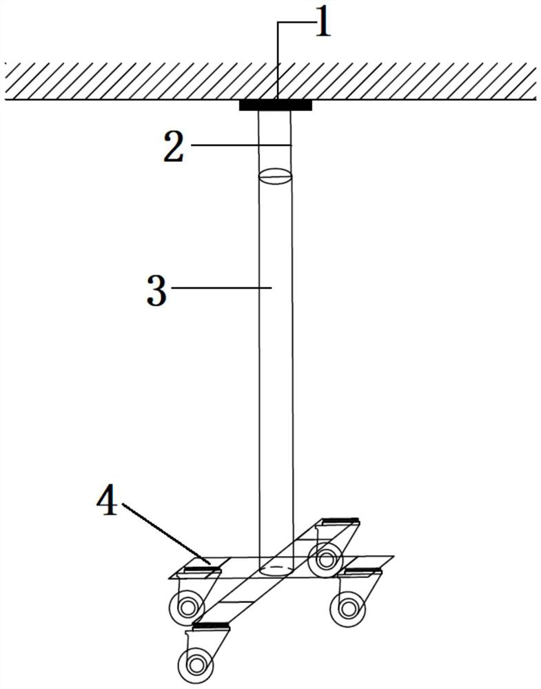
[0029] Embodiment 1: as figure 1 As shown, a movable jacking device includes a jacking plate 1, a hydraulic jacking device 2, a support member 3, and a movable base 4, and the jacking plate 1 is fixedly arranged on the top of the plunger of the hydraulic jacking device 2 , the hydraulic jacking device 2 is fixedly arranged on the top of the support 3 , and the bottom of the support 3 is arranged on the top of the movable base 4 .

Embodiment 2

[0030] Embodiment 2: as figure 1 , 2 As shown in and 6, a movable jacking device includes a jacking plate 1, a hydraulic jacking device 2, a support member 3, and a movable base 4, and the jacking plate 1 is fixedly arranged on the column of the hydraulic jacking device 2 The top of the plug, the hydraulic jacking device 2 is fixed on the top of the support 3, and the bottom of the support 3 is set on the top of the movable base 4;

[0031] The top surface of the plunger of the hydraulic jacking device 2 is fixedly connected to the bottom surface of the top strut 1 and the top surface of the plunger of the hydraulic jacking device 2 is located at the center of the bottom surface of the top strut 1;

[0032] The top of the support member 3 is fixedly provided with a fixed limiter 17 of the hydraulic jacking device, and the bottom of the hydraulic jacking device is arranged in the fixed limiter 17;

[0033] The fixed limiter 17 includes a fixed ring and a chassis, the chassis ...

Embodiment 3

[0036] Embodiment 3: as Figure 1~6 As shown, the structure of the movable jacking device of this embodiment is basically the same as that of the movable jacking device of embodiment 2, the difference is that:

[0037] The distance between the bottom surface of the fixed ring and the bottom surface of the chassis is 2-3mm, and the inner diameter of the fixed ring is 2-3mm larger than the outer diameter of the hydraulic jacking device;

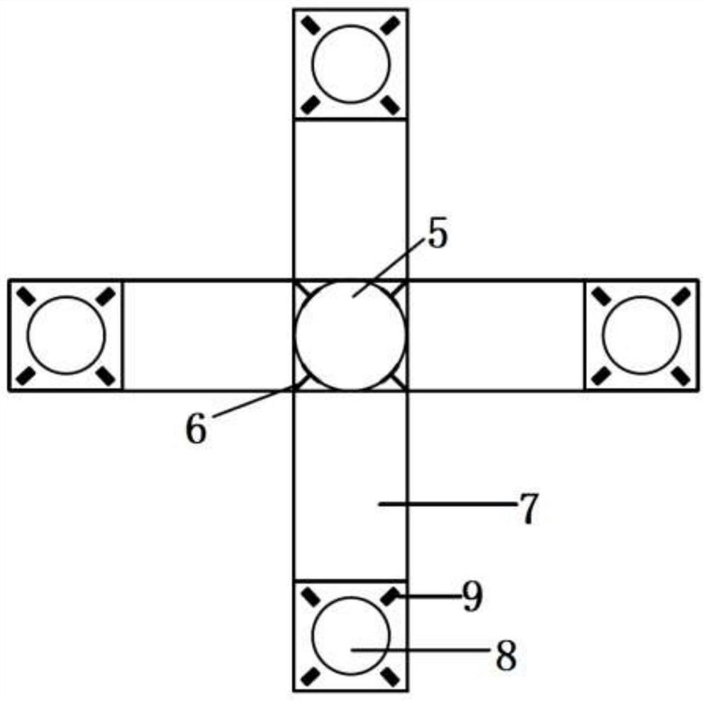
[0038] The inner edge of the limit chuck 5 is longer than the outer diameter of the support member 3, and the limit chuck 5 is evenly provided with several fixing members 6 of the support member 3, the fixing member 6 is perpendicular to the support member 3, and one end of the fixing member 6 In contact with the support member 3, the other end of the fixing member 6 extends to the outside of the limit chuck 5;

[0039] The side wall of the limit chuck 5 is uniformly provided with several through holes, and the hole wall is provided with equid...


PUM


Abstract

The invention relates to a movable back-jacking device, and belongs to the technical field of lifting devices. The movable back-jacking device comprises a top supporting plate, a hydraulic back-jacking device body, a supporting piece and a movable base, wherein the top supporting plate is fixedly arranged at the top end of a plunger of the hydraulic back-jacking device body, the hydraulic back-jacking device body is fixedly arranged at the top end of the supporting piece, and the bottom end of the supporting piece is arranged at the top end of the movable base. According to the movable back-jacking device, a fixing piece can be loosely and tightly adjusted to realize the assembly and disassembly of the supporting piece, the height of the hydraulic device is manually adjusted, the top supporting plate arranged in the upper portion can be used for dispersing the load force, the whole back-jacking device can realize 360-degree omnibearing movement through the movable base, and therefore,the back-jacking device has the effects of being adjustable, movable, easy and convenient to operate, high in adaptability and accurate in back jacking.

Description

technical field [0001] The invention relates to a movable jacking device, which belongs to the technical field of lifting devices. Background technique [0002] The traditional jacking device is composed of steel pipes and wooden beams. During the construction process, steel pipes or wooden beams of non-standard sizes are required, resulting in waste of materials and difficulty in turnover. The operation is cumbersome and affects the construction period. It is difficult to control the accuracy of partial jacking. , leading to inaccurate load distribution and affecting construction safety. Contents of the invention [0003] Aiming at the technical problems existing in the application of the existing movable jacking device, the present invention provides a movable jacking device, that is, a movable base is arranged at the bottom of the jacking device to realize the directional movement and precise positioning. [0004] The technical scheme that the present invention adopts...

Claims


Application Information

Patent Timeline
IPC IPC(8): E04G21/00
CPCE04G21/00
Inventor 朱恺杨召波文泉鸿谢亚
Owner CHINA CONSTR SECOND ENG BUREAU LTD
Why Eureka
Try Eureka