Granule fan heater

A heater and particle technology, applied in the direction of air heaters, combustion methods, fixed tubular conduit components, etc., can solve the problems of small heat exchange area of ​​the heat exchange device, potential safety hazards of the feeding device, and influence on the heat exchange effect. Good heating effect, ensuring the safety of the material box, and preventing blockage

Inactive Publication Date: 2020-11-13
浙江芝博科技有限公司
View PDF5 Cites 0 Cited by
  • Summary
  • Abstract
  • Description
  • Claims
  • Application Information

AI Technical Summary

Problems solved by technology

[0003] The heater is equipped with a combustion chamber for burning particulate matter. Because the feeding device is directly connected to the combustion chamber, due to the increase in temperature and pressure in the combustion chamber during the combustion process, tempering will occur, and the fuel in the feeding device will be ignited, and Also ignites the fuel in the storage tank, so this type of feeder is a safety hazard
[0004] After a period of use, there will be ash in the combustion chamber and coking due to insufficient combustion or condensation. If the coke and ash are not cleaned in time, they will gradually accumulate, which will affect the combustion effect
[0005] The high-temperature flue gas generated after combustion enters the heat exchange tube, the air around the heat exchange tube heats up, and the circulation fan blows out the heated air to achieve the effect of warm air. If the layer of soot is not cleaned for a long time, it will block the heat exchange tube, thereby affecting the heat exchange effect, and the heat exchange area of ​​the heat exchange device is small, and the heat exchange efficiency is too low

Method used


Image

  • Granule fan heater
  • Granule fan heater
  • Granule fan heater

Examples


Embodiment Construction

[0048] The following are specific embodiments of the present invention and in conjunction with the accompanying drawings, the technical solutions of the present invention are further described, but the present invention is not limited to these embodiments.

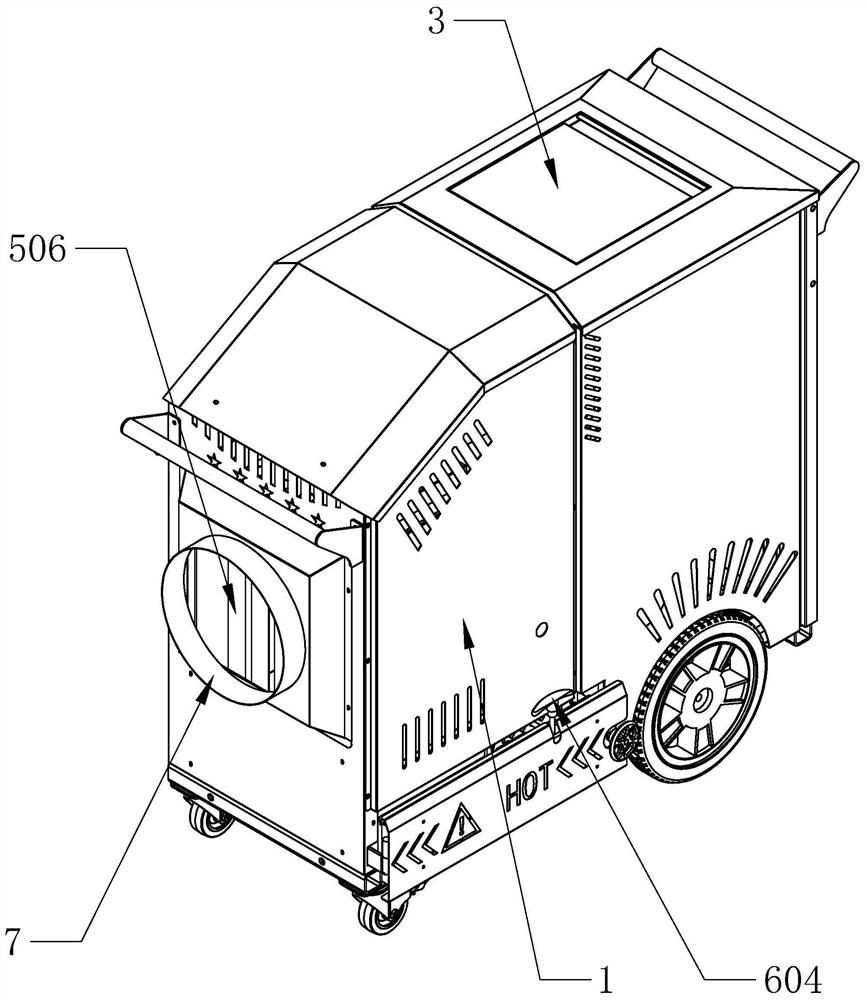
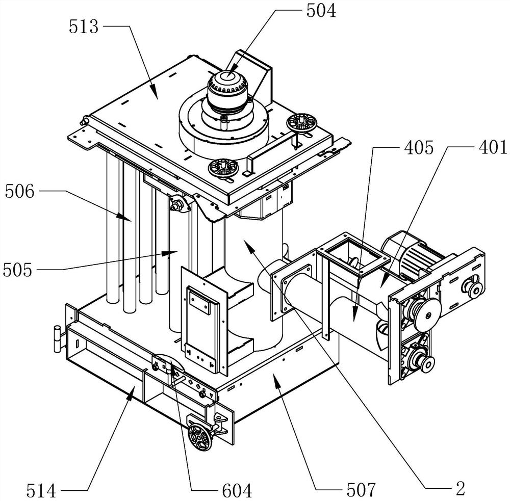
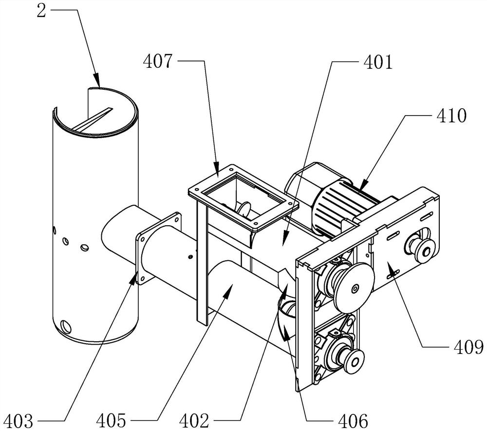
[0049] Such as figure 1 and figure 2 As shown, a particle heater according to the present invention includes a body 1, a combustion chamber 2 and a material box 3 are arranged in the body 1, and a feeding device is provided between the combustion chamber 2 and the material box 3, and the feeding device is used for The fuel in the material box 3 is sent to the combustion chamber 2, an anti-backfire structure is set between the feeding device and the combustion chamber 2, and a manual ash removal device is also provided at the bottom of the combustion chamber 2 to clean up the burned ashes The body 1 is also provided with a heat exchange device and a circulation fan, the heat exchange device communicates with the combustio...


PUM


Abstract

The invention provides a granule fan heater, and belongs to the technical field of combustion equipment. By adopting the granule fan heater, the problems of a current fan heater that a backfire phenomenon exists, cokes and ashes are accumulated in a combustion chamber, dust is accumulated in a heat dissipation pipe and a combustion effect is affected are solved. The granule fan heater comprises amachine body; a combustion chamber and a material box are arranged in the machine body; a material conveying device is arranged between the combustion chamber and the material box, and is used for conveying fuel in the material box into the combustion chamber; a backfire prevention structure is arranged between the material conveying device and the combustion chamber; a manual ash cleaning devicewhich is used for cleaning ashes remaining after combustion is arranged on the bottom of the combustion chamber; a heat exchanging device and a blower device are further arranged in the machine body;the heat exchanging device communicates with the combustion chamber; and the blower device is used for blowing hot air around the periphery of the heat exchanging device out of an air outlet to form hot wind. The granule fan heater has the advantages that the safety of the material box is ensured through the backfire prevention structure; the ashes at the bottom of the combustion chamber can be effectively cleaned through the manual ash cleaning device; and the heat exchanging area is increased through the heat exchanging device.

Description

technical field [0001] The invention belongs to the technical field of combustion equipment and relates to a particle heater. Background technique [0002] The particle heater refers to the use of agricultural and forestry waste particles such as straw as fuel, and adopts the semi-gasification combustion method, which effectively avoids the slagging of straw particles in the process of direct combustion, and adopts precise control of air distribution, feeding, Gasification and combustion, realizing efficient and clean combustion in the all-in-one machine. The air enters the body under the action of the circulating fan, is heated when passing through the heat exchange device, and finally forms warm air from the air outlet. [0003] The heater is equipped with a combustion chamber for burning particulate matter. Because the feeding device is directly connected to the combustion chamber, due to the increase in temperature and pressure in the combustion chamber during the combu...

Claims


Application Information

Patent Timeline
IPC IPC(8): F24H3/00F24H9/00F24H9/18F28D7/16F28F9/02F28F11/00F28G13/00F23J1/06F23K3/00
CPCF23J1/06F23K3/00F24H3/008F24H9/0052F24H9/189F28D7/16F28F9/02F28F11/00F28G13/00
Inventor 范群超
Owner 浙江芝博科技有限公司
Why Eureka
Try Eureka