Waste residue cooling device for steel and iron smelting and capable of improving cooling efficiency

A cooling efficiency and iron and steel smelting technology, applied in the field of waste slag cooling devices, can solve the problems of easy accumulation, lower effective utilization rate of cooling water, poor cooling effect, etc., and achieve the goal of increasing the stirring area, improving cooling efficiency, and improving cooling efficiency Effect

Inactive Publication Date: 2020-11-13
胡献敏
View PDF0 Cites 2 Cited by
  • Summary
  • Abstract
  • Description
  • Claims
  • Application Information

AI Technical Summary

Problems solved by technology

[0002] Blast furnace slag and other non-ferrous metal waste slag will be produced in the ironmaking furnace during iron and steel smelting. Some molten steel remains in this part of the waste slag, and the waste slag can also be used as smelting additives in steel plants after treatment, so it needs to be recycled. However, the temperature of the waste slag just out of the furnace is relatively high, so it is not suitable for direct use, so it needs to be cooled by a waste slag cooling device. It cannot be effectively dispersed, and it is easy to accumulate, resulting in poor cooling effect, and after the waste slag is sprayed with cooling water, the outer part of the waste slag will form a shell due to the low external temperature, preventing the cooling water from entering the interior of the waste slag, which in turn makes Reduced effective utilization of cooling water
[0003] Aiming at the deficiencies of the prior art, the present invention provides a waste slag cooling device for iron and steel smelting that can improve the cooling efficiency. The waste slag cooling device used in iron and steel smelting has the problems of low cooling efficiency of waste slag and low effective utilization of cooling water during use

Method used


Image

  • Waste residue cooling device for steel and iron smelting and capable of improving cooling efficiency
  • Waste residue cooling device for steel and iron smelting and capable of improving cooling efficiency
  • Waste residue cooling device for steel and iron smelting and capable of improving cooling efficiency

Examples


Embodiment Construction

[0022] The following will clearly and completely describe the technical solutions in the embodiments of the present invention with reference to the accompanying drawings in the embodiments of the present invention. Obviously, the described embodiments are only some, not all, embodiments of the present invention. Based on the embodiments of the present invention, all other embodiments obtained by persons of ordinary skill in the art without making creative efforts belong to the protection scope of the present invention.

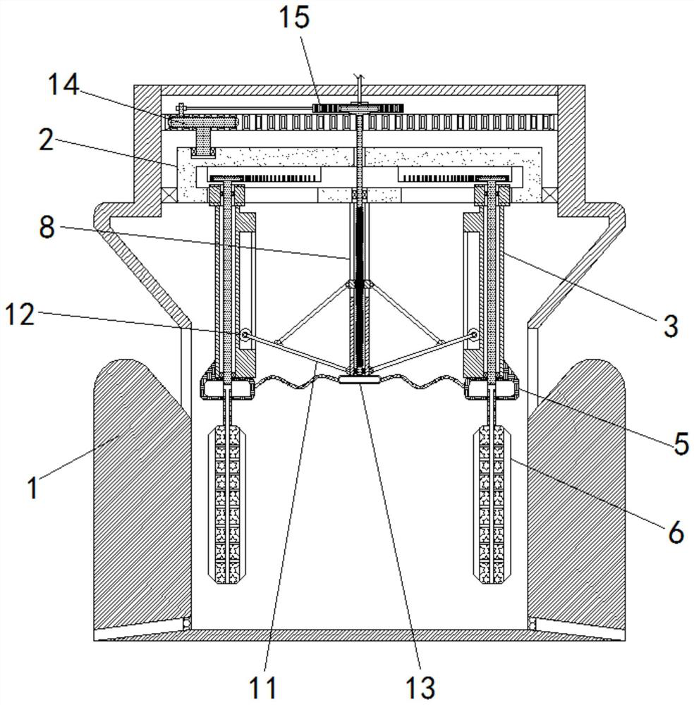
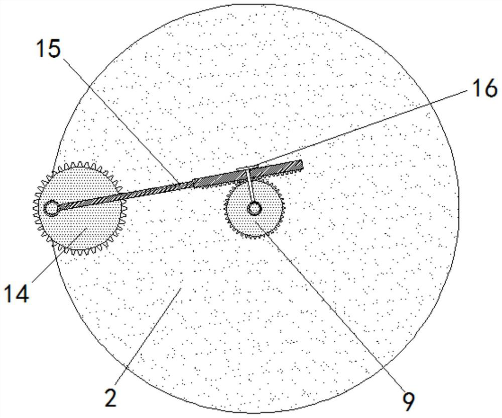
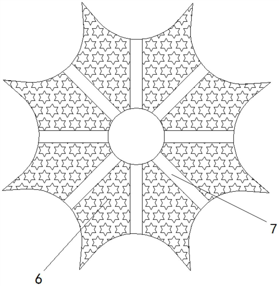
[0023] see Figure 1-6 , a waste slag cooling device for iron and steel smelting that can improve cooling efficiency, including a main body 1, the inner wall of the top of the main body 1 is provided with teeth matching the drive plate 14, so that when the drive plate 14 rotates, it can drive the carrying plate 2 Rotate, the upper part of the inner cavity of the main body 1 of the equipment is rotatably connected with the bearing plate 2, and the left and righ...


PUM


Abstract

The invention relates to the technical field of steel and iron smelting and discloses a waste residue cooling device for steel and iron smelting and capable of improving cooling efficiency. The wasteresidue cooling device comprises an equipment main body. A bearing disc is rotationally connected to the upper portion of an inner cavity of the equipment main body. Symmetrical guide columns are slidably connected to the lower end of the bearing disc. Transmission toothed rods extending into an inner cavity of the bearing disc are rotationally connected to inner cavities of the guide columns. A water storage disc is fixedly connected to the lower ends of the guide columns. According to the waste residue cooling device for steel and iron smelting and capable of improving the cooling efficiency, a driving disc rotates, thus a bearing disc rotates through teeth on the inner wall of the equipment main body, a breaking column is driven to do revolution and is synchronously matched with the driving disc to utilize rack, a threaded tooth rod is driven to rotate in a reciprocating mode, thus the guide columns on the two sides drive the breaking column to expand and contract in a reciprocatingmode, the breaking column rotates on the way, cooling water is released from the breaking column in a matched mode, thus the cooling efficiency of waste residues is promoted effectively, and the effective utilization ratio of the cooling water is increased.

Description

technical field [0001] The invention relates to the technical field of iron and steel smelting, in particular to a waste slag cooling device for iron and steel smelting that can improve cooling efficiency. Background technique [0002] Blast furnace slag and other non-ferrous metal waste slag will be produced in the ironmaking furnace during iron and steel smelting. Some molten steel remains in this part of the waste slag, and the waste slag can also be used as smelting additives in steel plants after treatment, so it needs to be recycled. However, the temperature of the waste slag just out of the furnace is relatively high, so it is not suitable for direct use, so it needs to be cooled by a waste slag cooling device. It cannot be effectively dispersed, and it is easy to accumulate, resulting in poor cooling effect, and after the waste slag is sprayed with cooling water, the outer part of the waste slag will form a shell due to the low external temperature, preventing the co...

Claims


Application Information

Patent Timeline
Patent Type & Authority Applications(China)
IPC IPC(8): F27D15/02B02C19/00
CPCB02C19/0056B02C19/0062F27D15/0286F27D2015/0293
Inventor 胡献敏
Owner 胡献敏
Why Eureka
Try Eureka