Camera shooting optical lens

An optical lens and optical total length technology, applied in the field of optical lenses, can solve the problems of inability to meet wide-angle, ultra-thin, optical power, lens spacing and unreasonable lens shape settings, and achieve the effect of excellent optical characteristics

Active Publication Date: 2020-11-13
CHANGZHOU RAYTECH OPTRONICS CO LTD
View PDF8 Cites 4 Cited by
  • Summary
  • Abstract
  • Description
  • Claims
  • Application Information

AI Technical Summary

Problems solved by technology

However, with the development of technology and the increase of diversified needs of users, as the pixel area of ​​the photosensitive device continues to shrink, and the system’s requirements for imaging quality continue to increase, the six-element lens structure gradually appears in the lens design. Common Although the six-element lens already has good optical performance, its focal power, lens spacing and lens shape settings are still unreasonable, resulting in a lens structure that cannot meet wide-angle, Ultra-thin design requirements

Method used


Image

  • Camera shooting optical lens
  • Camera shooting optical lens
  • Camera shooting optical lens

Examples


no. 1 approach )

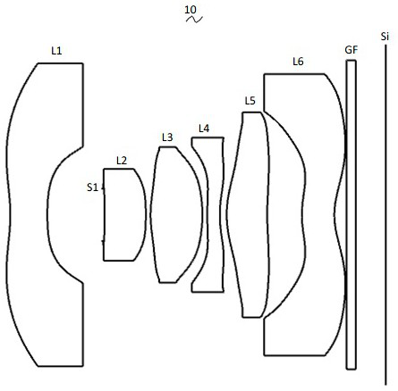
[0040] Referring to the accompanying drawings, the present invention provides an imaging optical lens 10 . figure 1 Shown is the imaging optical lens 10 of the first embodiment of the present invention. exist figure 1 Among them, the left side is the object side, and the right side is the image side. The imaging optical lens 10 includes six lenses in total. From the object side to the image side, there are first lens L1, aperture S1, second lens L2, third lens L3, The fourth lens L4, the fifth lens L5 and the sixth lens L6. An optical element such as an optical filter (filter) GF may be disposed between the sixth lens L6 and the image plane Si.

[0041]In this embodiment, the first lens L1 is made of glass, the second lens L2 is made of plastic, the third lens L3 is made of glass, the fourth lens L4 is made of plastic, the fifth lens L5 is made of plastic, and the sixth lens L6 Made of plastic. In other embodiments, each lens can also be made of other materials.

[0042] ...

no. 2 approach )

[0152] Figure 5 It is a schematic structural view of the imaging optical lens 20 in the second embodiment. The second embodiment is basically the same as the first embodiment. The meanings of the symbols in the following list are also the same as those in the first embodiment, so the same parts will not be repeated here. Only the differences are listed below.

[0153] In this embodiment, the object side surface of the second lens L2 is convex at the paraxial position.

[0154] Table 5 and Table 6 show design data of the imaging optical lens 20 according to the second embodiment of the present invention.

[0155] 【table 5】

[0156]

[0157]Table 6 shows the aspheric surface data of each lens in the imaging optical lens 20 according to the second embodiment of the present invention.

[0158] 【Table 6】

[0159]

[0160] Table 7 and Table 8 show the design data of inflection point and stagnation point of each lens in the imaging optical lens 20 .

[0161] 【Table 7】

...

no. 3 approach )

[0169] Figure 9 It is a schematic structural view of the imaging optical lens 30 in the third embodiment. The third embodiment is basically the same as the first embodiment. The meanings of the symbols in the following list are also the same as those in the first embodiment, so the same parts will not be repeated here. Only the differences are listed below.

[0170] In this embodiment, the object side surface of the second lens L2 is convex at the paraxial position.

[0171] Table 9 and Table 10 show design data of the imaging optical lens 30 according to the third embodiment of the present invention.

[0172] 【Table 9】

[0173]

[0174] Table 10 shows the aspheric surface data of each lens in the imaging optical lens 30 of the third embodiment of the present invention.

[0175] 【Table 10】

[0176]

[0177] Table 11 and Table 12 show the design data of inflection point and stagnation point of each lens in the imaging optical lens 30 .

[0178] 【Table 11】

[0179] ...


PUM


Abstract

The invention provides a camera shooting optical lens. The camera shooting optical lens comprises six lenses which are sequentially a first lens with negative refractive power, a second lens with positive refractive power, a third lens with positive refractive power, a fourth lens with negative refractive power, a fifth lens with positive refractive power and a sixth lens with negative refractivepower from the object side to the image side, wherein the Abbe number of the first lens is v1, the Abbe number of the third lens is v3, the on-axis distance from the image side surface of the fifth lens to the object side surface of the sixth lens is d10, the on-axis thickness of the sixth lens is d11, and the following relational expressions are satisfied, 60.00 </= v1 </= 90.00, 60.00 </= v3 </=90.00, 1.00 </= d10/d11 </= 5.00. The camera shooting optical lens has good optical performance and meets design requirements of ultra-wide angle and ultra-thinness.

Description

technical field [0001] The invention relates to the field of optical lenses, in particular to an imaging optical lens suitable for portable terminal devices such as smart phones and digital cameras, and imaging devices such as monitors and PC lenses. Background technique [0002] In recent years, with the rise of smart phones, the demand for miniaturized photographic lenses has been increasing, and the photosensitive devices of general photographic lenses are nothing more than photocoupled devices (Charge Coupled Device, CCD) or complementary metal oxide semiconductor devices (Complementary Metal -Oxide Semiconductor Sensor, CMOS Sensor), and due to the improvement of semiconductor manufacturing process technology, the pixel size of photosensitive devices has been reduced, and today's electronic products are developing with good functions and thin, light and small appearance. Therefore, it has Miniaturized camera lenses with good imaging quality have become the mainstream in...

Claims


Application Information

Patent Timeline
Patent Type & Authority Applications(China)
IPC IPC(8): G02B13/18G02B13/06
CPCG02B13/0045G02B13/06G02B9/62
Inventor 窦沂蒙
Owner CHANGZHOU RAYTECH OPTRONICS CO LTD
Why Eureka
Try Eureka