
A test method for dew point temperature of fuel cell humidification reaction gas

A technology of reaction gas and dew point temperature, applied in fuel cells, electrical components, circuits, etc., can solve the problems of dew point temperature deviation, uneconomical, high price of dew point instrument, achieve accurate calculation results, reduce measurement cost, and simple measurement equipment Effect

Active Publication Date: 2021-09-07
北京国鸿氢能科技有限公司 +1
View PDF0 Cites 0 Cited by
  • Summary
  • Abstract
  • Description
  • Claims
  • Application Information

AI Technical Summary

Problems solved by technology

Taking the air humidification of the fuel cell system as an example, at present, there are two methods commonly used in the prior art to determine the dew point temperature of the humidified gas: one is to directly define the temperature of the water passing through the membrane humidifier as the dew point temperature of the humidified gas Another approach is to use a dew point meter to measure the dew point temperature of the humidified gas; the disadvantage of the former is that the gas passing through the membrane humidifier is not necessarily saturated due to the difference in water vapor exchange, that is, the temperature of the humidified water is actually not Not equal to the dew point temperature of the humidified gas, resulting in inaccurate test results of this method
The disadvantage of the latter is that the existing dew point meters on the market are prone to water accumulation on the dew point probe when testing the dew point temperature, which will cause deviations in the measured dew point temperature value, and the accuracy of the test results cannot be guaranteed; and The dew point meter is usually expensive, which makes the test costly and uneconomical

Method used


Image

  • A test method for dew point temperature of fuel cell humidification reaction gas
  • A test method for dew point temperature of fuel cell humidification reaction gas

Examples


no. 1 example

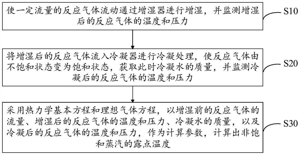
[0041] see figure 1 , the first embodiment of the present invention provides a method for testing the dew point temperature of the fuel cell humidification reaction gas, including:

[0042] S10, making a certain flow rate of reaction gas flow through the humidifier to perform humidification, and monitoring the temperature and pressure of the humidified reaction gas;

[0043] In this step, it should be noted that humidification refers to the process of increasing the humidity of the gas, which is a unit operation belonging to the process of heat and mass transfer. Generally speaking, humidification and dehumidification are used in conjunction with air conditioning to establish the required environment for production, life, and scientific experiments. In chemical production, the rapid cooling of high-temperature gas and the cooling of hot water all use direct gas-liquid contact for heat and moisture exchange. The principle is the same as that of humidification, and it is also a...

no. 2 example

[0066] In order to help understand the specific process of this program, the second embodiment of the present invention provides a complete calculation process that brings specific values ​​into the dew point temperature test method to examine the performance of a proton exchange membrane fuel cell stack test bench in a certain working condition Point air humidification capacity, calculate its dew point value as an example,

[0067] Before calculation, record the unhumidified air flow rate S as 2504slpm, the gas pressure after humidification P1=102kpa, temperature T1=63.5°C, condense the humidified gas to a certain temperature T2=5.8°C and Pressure P2=0kpa, collect the mass of condensed liquid water m=6661g and time t=32.9min, then calculate by thermodynamics and ideal gas equation:

[0068] (1) To calculate the saturated vapor pressure of condensed gas, use the formula: get p sat 2=0.916kpa; wherein, A, B, and C are constants corresponding to different gases in Antoine's e...

no. 3 example

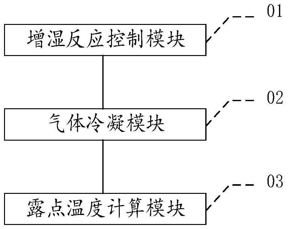
[0079] see figure 2 , the third embodiment of the present invention also provides a fuel cell humidification reaction gas dew point temperature testing system, including:

[0080]The humidification reaction control module 01 is used to make a certain flow rate of reaction gas flow through the humidifier for humidification, and monitor the temperature and pressure of the humidified reaction gas;

[0081] The gas condensation module 02 is used to flow the humidified reaction gas into the condenser for condensation treatment, so that the reaction gas changes from an unsaturated state to a saturated state, obtain the quality of condensed water at this time, and monitor the temperature of the condensed reaction gas and pressure;

[0082] The dew point temperature calculation module 03 is used to use the basic thermodynamic equation and the ideal gas equation to calculate the flow rate of the reaction gas before humidification, the temperature and pressure of the reaction gas afte...


PUM


Abstract

The invention discloses a method for testing the dew point temperature of humidification reaction gas of a fuel cell, which comprises: making a certain flow rate of reaction gas flow through a humidifier for humidification, and monitoring the temperature and pressure of the humidified reaction gas; The wet reaction gas flows into the condenser for condensation treatment, so that the reaction gas changes from an unsaturated state to a saturated state, obtain the quality of condensed water at this time, and monitor the temperature and pressure of the condensed reaction gas; use the basic thermodynamic equation and ideal The gas equation calculates the dew point temperature of unsaturated steam based on the flow rate of the reaction gas before humidification, the temperature and pressure of the reaction gas after humidification, the quality of condensed water, and the temperature and pressure of the reaction gas after condensation. The method for testing the dew point temperature of the fuel cell humidification reaction gas provided by the invention has simple measuring equipment, and the dew point temperature after gas humidification can be directly calculated through the basic laws of thermodynamics and the ideal gas state equation, so that the test result is accurate and reliable.

Description

technical field [0001] The invention relates to the technical field of fuel cells, in particular to a method for testing the dew point temperature of a fuel cell humidification reaction gas. Background technique [0002] As a kind of clean energy, fuel cells have been paid more and more attention in recent years, especially with the industrialization and mass production of fuel cells or systems, the accuracy and controllability of the operating conditions of fuel cell stacks or systems are getting higher and higher. People pay more and more attention, especially the test of the dew point temperature of the reaction gas after humidification has always been a relatively big problem. Taking the air humidification of the fuel cell system as an example, at present, there are two methods commonly used in the prior art to determine the dew point temperature of the humidified gas: one is to directly define the temperature of the water passing through the membrane humidifier as the d...

Claims


Application Information

Patent Timeline
Patent Type & Authority Patents(China)
IPC IPC(8): H01M8/0438H01M8/04119H01M8/04992
CPCH01M8/04126H01M8/04388H01M8/04395H01M8/04432H01M8/04992Y02E60/50
Inventor 崔士涛邓存柏瞿丽娟陈允至黄志华
Owner 北京国鸿氢能科技有限公司
Learn More