contact microphone

A microphone and contact technology, which is applied in the direction of sensors, bone conduction transducer hearing equipment, active noise cancellation hearing equipment, etc., can solve the problems of poor anti-noise effect, large volume, and low sensitivity

Active Publication Date: 2022-04-05
JIANGXI LIANCHUANG HONGSHENG ELECTRONICS
View PDF7 Cites 0 Cited by
  • Summary
  • Abstract
  • Description
  • Claims
  • Application Information

AI Technical Summary

Problems solved by technology

[0005] The purpose of the present invention is to propose a contact microphone to solve the problems that the contact microphone in the prior art has relatively large volume, low sensitivity and poor anti-noise effect

Method used


Image

  • contact microphone
  • contact microphone
  • contact microphone

Examples


Embodiment 1

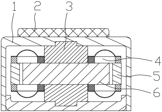
[0036] refer to Figure 1 to Figure 6 , the first embodiment of the present invention provides a contact microphone, including a housing 1, a circuit board 2 and a support block 3 placed inside the housing 1, a suspension 4, a reverse induction coil assembly 5 and a magnet 6. The circuit board 2 is arranged on the top of the housing 1, the support block 3, the suspension 4, the reverse induction coil assembly 5 and the magnet 6 are all arranged coaxially, and the reverse induction coil The component 5 is connected to the circuit board 2 and is set outside the magnet 6. The reverse induction coil component 5 includes an upper coil 511 and a lower coil 512 that are reversely wound and connected together. The magnet 6 passes through the support The block 3 is fixedly installed in the housing 1, and the two groups of suspension parts 4 are sleeved on the support block 3, and are arranged symmetrically at the upper and lower ends of the magnet 6, and the two groups of the suspensio...

Embodiment 2

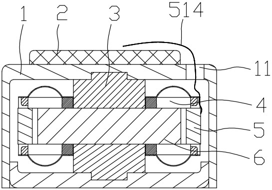
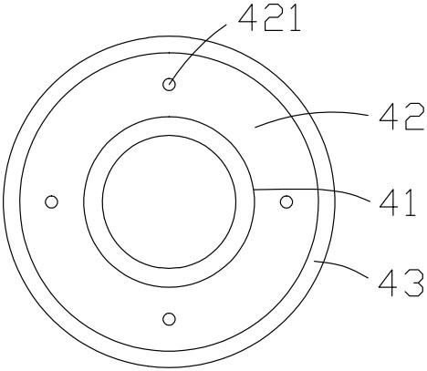
[0049] refer to Figure 7 , the second embodiment of the present invention provides a contact microphone, its implementation content is basically the same as that of embodiment 1, the difference is that: the second lead wire 514 is outside the reverse induction coil assembly 5, and the first The two lead wires 514 pass through above the connecting body 42, are pulled by glue, and fixed on the inner fixing ring 41 with glue, and then pass through the lead hole 11 of the housing 1 and the threading hole 21 of the circuit board 2 Go out and spot weld on the circuit board 2.

Embodiment 3

[0051] refer to Figure 8 , the third embodiment of the present invention provides a contact microphone, its implementation content is basically the same as that of embodiment 1, the difference is that: the second lead wire 514 is inside the reverse induction coil assembly 5, and the first Two lead wires 514 pass below the connecting body 42, the second lead wire 514 is in an arc shape, passes through the magnet 6 and is bonded to the magnet 6 by glue, and then passes through the inner fixing ring 41 The first balance hole 411 finally passes through the lead wire hole 11 of the housing 1 and the wiring hole 21 of the circuit board 2 , and is spot welded on the circuit board 2 .


PUM


Abstract

The invention provides a contact microphone, which includes a shell, a circuit board, a support block placed inside the shell, two sets of suspension parts, a reverse induction coil assembly and a magnet. The reverse induction coil assembly includes a reverse winding and is connected to The upper coil and the lower coil together, the magnet is fixedly installed in the casing through the support block, and the two sets of suspension parts are sleeved on the support block, symmetrically arranged at the upper and lower ends of the magnet. The suspension includes an inner fixing ring, an outer fixing ring and a connecting body. Two sets of suspension parts with the same stiffness coefficient are symmetrically arranged, and the air conduction noise forces they bear cancel each other out, which significantly improves the noise resistance of the product; Through the up and down vibration of the induction coil assembly reversely wound, the two poles of the magnet are synchronously cut to obtain two positively superimposed motional electromotive force outputs, and the conversion of the vibration signal to the electrical signal is completed, which greatly improves the sensitivity of the product; two groups The suspension and reverse induction coil assembly form an elastic bladder structure that provides high frequency resonance.

Description

technical field [0001] The invention relates to the field of microphones, in particular to a contact microphone. Background technique [0002] In the field of communication technology, a microphone is a device responsible for converting the voice and sound signals emitted by the speaker into electrical signals for output. Microphones are generally divided into two categories: air conduction microphones and contact microphones. The air-conduction microphone is an instrument that directly converts the received voice signal transmitted by air vibration into an electrical signal output; the contact microphone is close to the head or neck of the human body, and picks up the skull or throat when the person makes a sound. An instrument that generates slight vibrations and converts them into electrical signals for output. [0003] Contact microphones are divided into single-membrane structure and double-membrane structure. The existing single-membrane contact microphone structure ...

Claims


Application Information

Patent Timeline
Patent Type & Authority Patents(China)
IPC IPC(8): H04R9/02H04R9/04H04R9/06
CPCH04R9/025H04R9/04H04R9/06H04R2460/01H04R2460/13
Inventor 邓旭东叶灵燚朱孟张俊平
Owner JIANGXI LIANCHUANG HONGSHENG ELECTRONICS
Why Eureka
Try Eureka