[0027] The following will clearly and completely describe the technical solutions in the embodiments of the present invention in conjunction with the accompanying drawings in the embodiments of the present invention. Obviously, the described embodiments are only a part of the embodiments of the present invention, rather than all the embodiments. The embodiments of the present invention, and all other embodiments obtained by those of ordinary skill in the art without creative work, fall within the protection scope of the present invention.
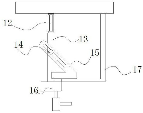
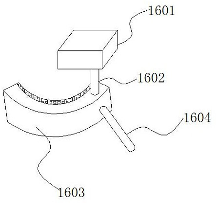
[0028] See Figure 1-6 , The present invention provides a technical solution: a processing equipment with real-time adjustment of the welding angle for the production of four-way air-conditioning valves, comprising a machine table 1, a first transmission rod 10, a bracket 11, a second transmission rod 18 and a fixed frame 23. A telescopic rod 2 is installed on the top of the table 1, and a sliding rod 3 is installed through the inside of the telescopic rod 2, a material rack 4 is installed on the surface of the sliding rod 3, and the side of the material rack 4 is offset from the mounting limit plate 5, the limit plate 5 The inclined plane block 6 is installed inside, and the side of the inclined plane block 6 is installed with a force rod 27, the bottom of the inclined plane block 6 is installed with a push rod 28, the inclined plane block 6 and the force rod 27 are connected by a slot, and the inclined plane block 6 passes The force rod 27 drives the push rod 28 to form a telescopic structure. Through the arrangement of the inclined plane block 6 and the push rod 28, when the material rack 4 pushes the force rod 27 forward, the inclined plane block 6 will drive the push rod 28 to move downward and warp. The rod 8 will therefore push the support block 7 up to contact the bottom surface of the material rack 4, and push the material rack 4 to be parallel to the fixed frame 23, and the bottom of the push rod 28 is fitted with a tilting rod 8, and the top of the tilting rod 8 is installed There is a support block 7, the surface of the support block 7 is designed to be inclined at 30°, and the support block 7 forms a telescopic structure through the push rod 28 and the rocking rod 8. The first transmission rod 10 is located on the side of the material rack 4, the material rack 4 and the sliding rod 3. It is a sliding connection, and the material rack 4 pushes the first transmission rod 10 through the first hydraulic rod 9 to form a sliding structure. Through the arrangement of the first transmission rod 10 and the first hydraulic rod 9, when the first hydraulic rod 9 drives the first transmission rod When 10 moves forward, the material rack 4 will therefore move forward along the sliding rod 3 to complete the positioning and conveying of the material, and the first hydraulic rod 9 is installed at the tail of the first transmission rod 10, and the bracket 11 is installed at the limit. A second hydraulic rod 12 is installed on the side of the position plate 5 and the top inner side of the bracket 11, and a baffle 17 is installed on the side of the second hydraulic rod 12 to deviate from the side. Through the arrangement of the second hydraulic rod 12 and the slider 15, when the second hydraulic rod 12 When the hydraulic rod 12 extends downward, the slider 15 can only move forward due to the baffle 17, so that the welding device 16 can slide to the position where welding is required while descending. The bottom of the second hydraulic rod 12 is installed There is a connecting plate 13, and a fixing block 14 is installed on the surface of the connecting plate 13, a sliding block 15 is installed on the surface of the fixing block 14, and a welding device 16 is installed at the bottom of the sliding block 15. The welding device 16 includes a supporting plate 1601, a welding plate 1602 The rotating ring 1603 and the rotating rod 1604, the support plate 1601 is located at the bottom of the connecting plate 13, and the bottom of the support plate 1601 is installed with a rotating ring 1603, the left side of the rotating ring 1603 is installed with a welding plate 1602, and the right surface of the rotating ring 1603 A rotating rod 1604 is installed, the rotating ring 1603 and the supporting plate 1601 are in sliding connection, and the rotating ring 1603 forms a sliding structure at the bottom of the supporting plate 1601 through the rotating rod 1604, and the connection relationship between the rotating ring 1603 and the supporting plate 1601 is arranged to make the When the equipment is welding the four-way valve, the rotating rod 1604 can be controlled to adjust the welding angle of the welding plate 1602. The slider 15 is slidably connected to the fixed block 14, and the slider 15 is driven by the second hydraulic rod 12 to drive the welding device 16 to form a sliding structure. The second transmission rod 18 is located on the side of the welding device 16, and the bottom of the second transmission rod 18 is installed with a movable Rod 19, the bottom of the movable rod 19 is installed with a valve 20. Through the arrangement of the movable rod 19 and the valve 20, since the movable rod 19, the second transmission rod 18 and the valve 20 are all shaft-connected, when the second hydraulic rod 12 stretches up and down Therefore, the valve 20 is driven to form an open or closed state by turning the switch of the valve 20, and the bottom of the valve 20 is equipped with a water spray port 21. The movable rod 19 is connected with the second transmission rod 18 and the valve 20, and the movable rod 19 The valve 20 is driven by the second hydraulic lever 12 to form a closed structure. A water tank 22 is installed on the side of the valve 20, a fixed frame 23 is located on the inner surface of the left side of the bracket 11, and a non-slip block 24 is installed inside the fixed frame 23. The side of the non-slip block 24 A snap ring 26 is installed deviatingly, and a pull rod 25 is installed on the surface of the snap ring 26. The pull rod 25 is installed through the surface of the fixed frame 23. The pull rod 25 and the snap ring 26 are integrally designed to surround the snap ring 26 in a semicircular shape, and the snap ring 26 through the tie rod 25 constitutes a tensioning structure.
[0029] Working principle: The four-way valve of the air conditioner produces processing equipment with real-time adjustment of welding angle. When using, the main pipe of the four-way valve is first inserted into the fixing frame 23. Under the action of the snap ring 26 and the anti-skid block 24, the main pipe will be fixed. , Insert the three branch pipes into the fixed frame 23. Under the action of the first hydraulic rod 9, the first transmission rod 10 will bring the animal material rack 4 to slide on the sliding rod 3. When the material rack 4 touches the receiver during the sliding process When the force rod 27 is used, because the force rod 27 and the inclined block 6 are slidingly connected, when the force rod 27 moves forward, the inclined block 6 will drive the push rod 28 to move downward, and when the push rod 28 touches the tilt rod When 8 is on the left side, the right side of the rocking rod 8 will be tilted upwards, and the supporting block 7 will push the three branch pipes of the four-way valve into the main pipeline, and then the second hydraulic rod 12 will drive the fixed block 14 to move down, and the welding device 16 will also move downward because of the sliding connection between the slider 15 and the fixed block 14, so while the connecting plate 13 moves downward, the slider 15 will also drive the welding device 16 closer to the workpiece, when the welding plate 1602 When the contact position between the main pipe and the branch pipe is reached, the welding will start. Since the rotating ring 1603 and the supporting plate 1601 are slidingly connected, the welding direction of the welding plate 1602 can be adjusted by controlling the rotating rod 1604 during the welding process. The welding is finished Later, the second hydraulic lever 12 will drive the connecting plate 13 upward, and the welding device 16 will gradually move away from the workpiece. Since the second transmission rod 18 is connected with the valve 20 as a shaft, when the welding device 16 moves upward, the valve 20 will be controlled. In the open state, the water in the water tank 22 will be sprayed from the water nozzle 21 to the welding point to accelerate cooling. The above is the whole working principle of the processing equipment with real-time adjustment of the welding angle produced by the four-way valve of the air conditioner.
[0030] Although the embodiments of the present invention have been shown and described, those of ordinary skill in the art can understand that various changes, modifications, and substitutions can be made to these embodiments without departing from the principle and spirit of the present invention. And variations, the scope of the present invention is defined by the appended claims and their equivalents.