Automatic polishing equipment for surface of building wood

A wood surface, automatic polishing technology, applied in the field of wood processing, can solve the problems of inconvenient cooling of the wood surface, inconvenient cleaning of sawdust, etc.

Inactive Publication Date: 2020-11-17
余光亮
View PDF10 Cites 10 Cited by
  • Summary
  • Abstract
  • Description
  • Claims
  • Application Information

AI Technical Summary

Problems solved by technology

[0004] The purpose of the present invention is to solve the problems in the prior art that it is inconvenient to cool down the wood surface during the polishing process, and it is inconvenient to clean up the wood chips produced by the polishing process, and proposes an automatic polishing equipment for the wood surface used in construction

Method used


Image

  • Automatic polishing equipment for surface of building wood
  • Automatic polishing equipment for surface of building wood
  • Automatic polishing equipment for surface of building wood

Examples


Embodiment 1

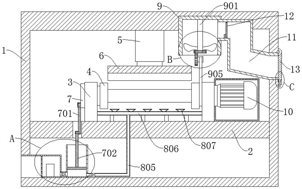
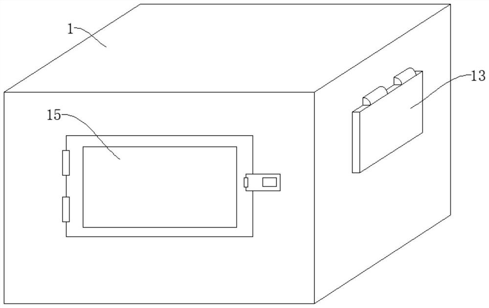
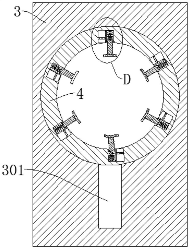
[0039] refer to Figure 1-7, an automatic polishing device for building wood surfaces, comprising a box body 1, a box door 15, the box door 15 is connected to the side wall of the box body 1 through hinges, the box body 1 is fixedly connected with a mounting plate 2, and the box body 1 The upper end of the interior is fixedly connected with an electric telescopic rod 5, the telescopic end of the electric telescopic rod 5 is fixedly connected with a polishing machine 6, two sets of support frames 3 are symmetrically fixedly connected to the mounting plate 2, and the support frame 3 is rotatably connected with a fixed shaft 4. One of the fixed rotating shafts 4 is provided with a drive motor 10, and the other fixed rotating shaft 4 is fixedly connected with a crank 7. The fixed rotating shaft 4 is provided with multiple sets of first air chambers 401, and the first air chambers 401 are slidingly connected with piston rods. 402, the end of the piston rod 402 located in the first ...

Embodiment 2

[0042] refer to Figure 1-7 , a kind of automatic polishing equipment for the surface of wood used in construction, which is basically the same as that in Embodiment 1, furthermore, a second gas bin 404 is arranged next to each first gas bin 401, and the first gas bin 401 is connected to the second gas bin 401. The bin 404 is connected by a conduit, and the second air bin 404 is slidably connected with a slider 405. The slider 405 is closely attached to the second air bin 404 and slides freely. When the fixed shaft 4 is rotating, the slider 405 is under the action of centrifugal force. Slide in the second air chamber 404, press the air in the second air chamber 404 into the first air chamber 401 through the conduit, and then push the piston rod 402 to further push the clamping block 406, so that the clamping block 406 and the polished The wood tightens further.

Embodiment 3

[0044] refer to Figure 1-7 , a kind of automatic polishing equipment for building wood surfaces, which is basically the same as that of Embodiment 1, furthermore, the air injection pipe 806 is located between the two fixed rotating shafts 4, and the nozzle 807 faces the area between the two fixed rotating shafts 4, which is convenient For cooling wood during polishing process.


PUM


Abstract

The invention discloses automatic polishing equipment for the surface of building wood, and belongs to the field of wood. The automatic polishing equipment for the surface of the building wood comprises a box body and a box door, wherein the box door is connected to the side wall of the box body through hinges; an installing plate is fixedly connected into the box body; an electric telescopic rodis fixedly connected to the upper end in the box body; a polishing machine is fixedly connected to the telescopic end of the electric telescopic rod; two groups of supporting frames are symmetricallyand fixedly connected onto the installing plate; fixed rotating shafts are rotatably connected onto the supporting frames; and a driving motor is arranged on one of the fixed rotating shafts. According to the polishing equipment for the surface of the building wood provided by the invention, the surface of the wood is conveniently cooled through the arrangement of a crank, a reciprocating mechanism, an air cylinder, a piston piece, an air spraying pipe and a spraying head; wood chips in the box body are conveniently pumped out through the arrangement of a dust suction box, the rotating shafts,fan blades, a driven gear and a bevel gear; and the wood is conveniently clamped and fixed through the arrangement of a first air bin, a piston rod and a spring.

Description

technical field [0001] The invention relates to the technical field of wood processing, in particular to an automatic polishing device for building wood surfaces. Background technique [0002] Polishing refers to the use of mechanical, chemical or electrochemical effects to reduce the surface roughness of the workpiece to obtain a bright and smooth surface. It is a modification of the surface of the workpiece using polishing tools and abrasive particles or other polishing media. Polishing The dimensional accuracy or geometric shape accuracy of the workpiece cannot be improved, but for the purpose of obtaining a smooth surface or mirror luster. Before use, construction wood often needs to be polished and cut by carpenters into decorative panels or connecting panels with certain decorative effects. Woodworkers often use polishing machines to polish wood. Existing polishing equipment generates too much heat during the friction between the grinding wheel and the wood surface dur...

Claims


Application Information

Patent Timeline
Patent Type & Authority Applications(China)
IPC IPC(8): B24B29/02B24B55/02B24B55/06B24B55/12B24B41/06B24B47/12B24B47/22
CPCB24B29/02B24B41/06B24B47/12B24B47/22B24B55/02B24B55/06B24B55/12
Inventor 余光亮
Owner 余光亮
Why Eureka
Try Eureka