A textile lifting device

A lifting device and textile technology, applied in textiles and papermaking, textile material cutting, transportation and packaging, etc., can solve the problems of textile workers' influence, spinning thread breakage, speeding up textile efficiency, etc., to improve accuracy, The effect of reducing the chance of breakage

Active Publication Date: 2022-04-08
湖南曼妮科技股份有限公司
View PDF16 Cites 0 Cited by
  • Summary
  • Abstract
  • Description
  • Claims
  • Application Information

AI Technical Summary

Problems solved by technology

[0003] Chinese patent document CN201821246420.8 discloses a textile pulling device, which records that "by setting a telescopic square tube, it can effectively avoid thread breakage due to excessive pulling force during the textile process, and at the same time, it can It is more convenient to pull the spinning thread and speed up the efficiency of spinning.” However, the structure of this scheme is simple, and the spinning thread can only be pulled up simply, and the pulling effect is not good, and if there is too much lifting, it will be very difficult. It is easy to cause the thread to break, and it is impossible to deal with the breakage of the thread. If the thread is not found to be broken in the first place, it may cause great problems in the spinning work. At the same time, the surface of the thread will be attached during the production process. A large amount of dust, a large amount of dust is easy to swell during the weaving process, and then diffuses in the air, which is easy to affect the workers in the weaving work, and when the existing technology needs to cut the spun thread, the worker needs to use a shearing tool to cut the spun thread, The operation is troublesome, and the existing thread cutting device generally only has one blade. Cutting the thread by one blade may cause fluffing or bifurcation at the incision of the thread, which is not conducive to workers installing the thread on the textile next time. inside the device

Method used


Image

  • A textile lifting device
  • A textile lifting device
  • A textile lifting device

Examples


Embodiment Construction

[0031] The technical solutions of the present invention will be further described below in conjunction with the accompanying drawings and through specific implementation methods.

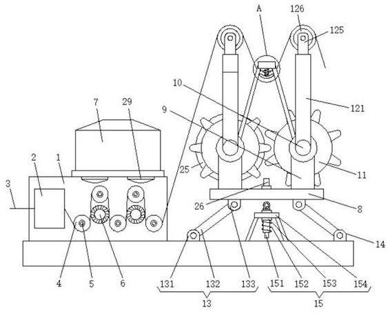
[0032] Such as Figure 1-9 As shown, a textile lifting device is provided in the embodiment, including a side plate 1, a dust collection box 7, a support plate 8, a gear 11 and a first linkage mechanism 13, and the front and rear sides of the lower surface of the support plate 8 are Both are fixedly connected with a first link mechanism 13, and the other end of the first link mechanism 13 is fixedly connected with the upper surface of the bottom plate, and the front and rear sides of the lower surface of the support plate 8 are fixedly connected with a second link mechanism 14, The bottom end of the second link mechanism 14 is fixedly connected to the upper surface of the slide block 28, and the slide block 28 is slidably connected in the first chute 16 provided on the upper surface of the bottom pl...


PUM


Abstract

The invention discloses a textile lifting device, which belongs to the field of textile devices, and comprises a side plate, a dust collecting box, a support plate, a gear and a first link mechanism, and the front and rear sides of the lower surface of the support plate are fixedly connected with a first A link mechanism, the other end of the first link mechanism is fixedly connected to the upper surface of the bottom plate, and the front and rear sides of the lower surface of the support plate are fixedly connected to the second link mechanism. The textile pulling device provided by the present invention is provided with a motor, a gear and a pulling mechanism, and the two lifting mechanisms can support the spinning thread, thereby realizing pulling the spinning thread. When the motor works, a gear can be driven to rotate, and the Changing the overall position of the pulling mechanism can also change the pulling effect of the spinning thread. By using the effect of two-stage adjustment, the accuracy of pulling the spinning thread is improved, so as to adjust the pulling degree that is more suitable for the spinning thread , to reduce the chance of yarn breakage.

Description

technical field [0001] The invention relates to the field of textile devices, more specifically, to a textile pulling device. Background technique [0002] Textile equipment is an indispensable and important equipment in human history. With the progress and development of society, textile equipment is becoming more and more advanced. It can weave various fiber materials into cloth shapes. The progress of textile equipment has greatly improved the quality of textile flats. And greatly reduce the cost of textile manufacturing, and better promote the rapid development of the textile industry. [0003] Chinese patent document CN201821246420.8 discloses a textile pulling device, which records that "by setting a telescopic square tube, it can effectively avoid thread breakage due to excessive pulling force during the textile process, and at the same time, it can It is more convenient to pull the spinning thread and speed up the efficiency of spinning.” However, the structure of t...

Claims


Application Information

Patent Timeline
Patent Type & Authority Patents(China)
IPC IPC(8): B65H59/36B65H71/00B65H54/70D06H7/00
CPCB65H59/36B65H71/00B65H54/70D06H7/00B65H2701/31
Inventor 郑才均洪文彬
Owner 湖南曼妮科技股份有限公司
Why Eureka
Try Eureka