
Road surface indentation equipment for road construction

A road construction and indentation technology, which is applied in the direction of roads, roads, road repairs, etc., can solve the problems of small labor force, large labor force, easy fatigue, etc., and achieve the effect of beautiful appearance, long life and material saving

Active Publication Date: 2020-11-17
南联建设集团有限公司
View PDF6 Cites 1 Cited by
  • Summary
  • Abstract
  • Description
  • Claims
  • Application Information

AI Technical Summary

Problems solved by technology

[0006] In order to overcome the current problem that two people are required to cooperate with the road surface indentation work, the labor force is relatively large, and manual long-term operation is easy to get tired and the work efficiency is difficult to guarantee. The technical problem to be solved by the invention is to provide a kind of Road surface indentation equipment for road construction without fatigue and high work efficiency after long hours of work

Method used


Image

  • Road surface indentation equipment for road construction
  • Road surface indentation equipment for road construction
  • Road surface indentation equipment for road construction

Examples


Embodiment 1

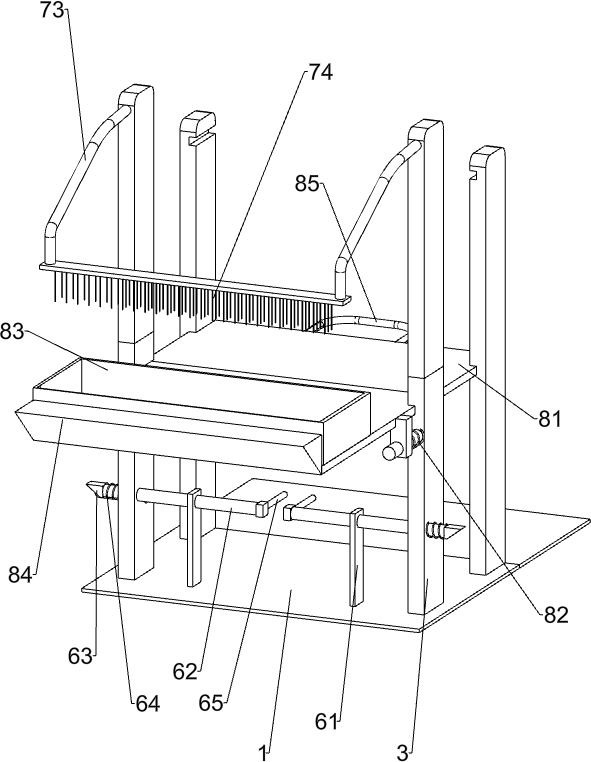
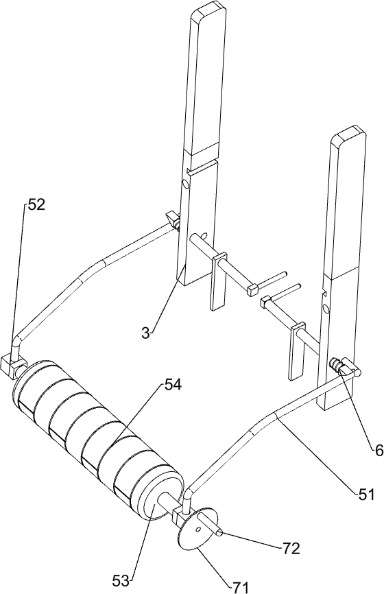
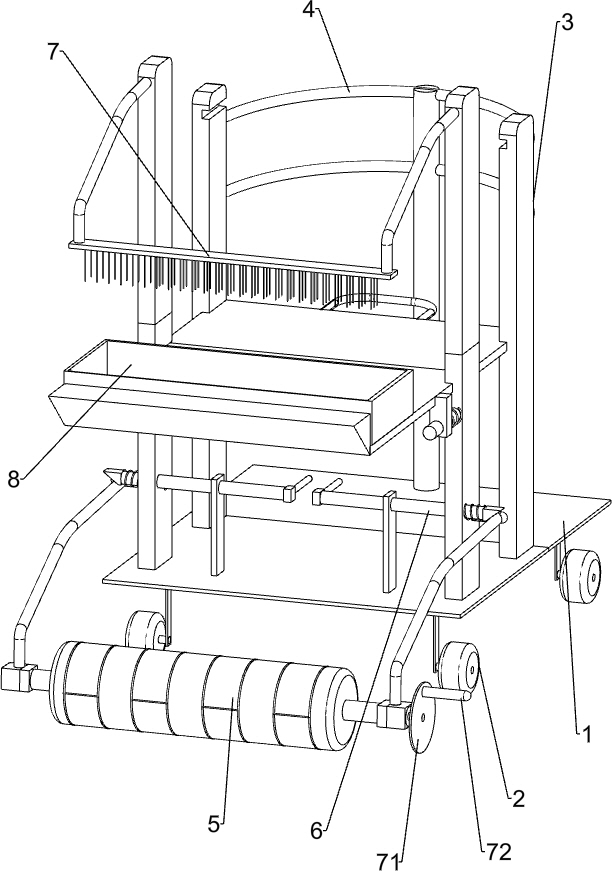
[0024] A road surface indentation equipment for road construction, such as Figure 1-3 As shown, it includes a placement board 1, wheels 2, bracket 3, first handle 4, seam pressing assembly 5 and limit assembly 6, the bottom of placement board 1 is connected with wheels 2, and the top of placement board 1 is provided with two Bracket 3, the first handle 4 is connected to the rear end of the placement plate 1, the front end of the first handle 4 is connected to the two brackets 3 on the rear side, the front side of the bottom of the bracket 3 is provided with a crimping assembly 5, and the lower sides of the two brackets 3 at the front end are connected Limit component 6.

[0025] The seam pressing assembly 5 includes a first curved rod 51, a briquetting block 52, a cylinder 53 and a seam leaving mold 54. The bottoms of the two supports 3 on the front side are rotatably connected with the first curved rod 51, and the front ends of the first curved rod 51 are provided with Ther...

Embodiment 2

[0029] On the basis of Example 1, such as Figure 2-3 As shown, a cleaning assembly 7 is also included. The cleaning assembly 7 includes a disc 71, a handle 72, a second curved rod 73 and a brush 74. The right side of the cylinder 53 is fixedly connected with a disc 71, and the eccentric position on the right side of the disc 71 is A handle 72 is connected, and two second curved rods 73 are arranged on the top front ends of the two brackets 3 on the front side, and a brush 74 is installed between the front ends of the two second curved rods 73 .

[0030] When the short inclined block 63 blocked the first curved bar 51, the hairbrush 74 was in contact with the cylinder 53 and the seam leaving mold 54, and the staff rotated the disc 71 by turning the handle 72, and the cylinder 53 and the seam leaving mold 54 rotated thereupon. Under the action of the brush 74, the cement adhering to the roller 53 and the seam leaving mold 54 is brushed off, and the roller 53 and the seam leavin...


PUM


Abstract

The invention relates to road construction equipment, in particular to road surface indentation equipment for road construction. The technical problem to be solved by the invention is to provide the road surface indentation equipment for road construction, which is relatively small in labor force, not easy to fatigue after long-time work and high in working efficiency. In order to solve the technical problem, the road surface indentation equipment for road construction provided by the invention comprises a placing plate, wherein the bottom of the placing plate is connected with wheels; a bracket which is connected to the placing plate; a first handle which is connected to one end of the placing plate and is connected with one side of the support; and a seam pressing assembly which is connected to one side of the bottom of the support, and the limiting assembly is connected to the support. The road surface indentation equipment has the advantages that the creasing equipment is moved bypushing the first handle to be matched with the wheels, a road is crewed under the action of the creasing assembly, and a worker can easily perform creasing on the road.

Description

technical field [0001] The invention relates to a road construction equipment, in particular to a road surface indentation equipment for road construction. Background technique [0002] Road expansion joints, or expansion joints, refer to a structural joint set at an appropriate part along the construction joint direction of a building or structure in order to prevent cracks or damage to the structure due to climate temperature changes. The expansion joint is to divide the building components above the foundation such as walls, floors, roofs (except wooden roofs) into two independent parts, so that buildings or structures can be horizontally expanded along the long direction. [0003] At present, two people usually hold one end of the indentation roller in the indentation work on the road surface, and operate the indentation roller to roll on the cement road surface that is not completely dry, and press the indentation through the indentation roller. In this way, two people ...

Claims


Application Information

Patent Timeline
Patent Type & Authority Applications(China)
IPC IPC(8): E01C23/02B08B1/02B08B15/04B08B1/20
CPCE01C23/02B08B15/04B08B1/20B08B1/12Y02A30/60
Inventor 徐亚卿
Owner 南联建设集团有限公司
Learn More