
Continuous construction method for fibers at joint of concrete structure

A technology of concrete structure and construction method, which is applied in the direction of building components, building structure, and building materials processing, etc., can solve the problems of increasing the crack strength of joints, reducing the crack strength of joints, and increasing the difficulty of construction, etc. To achieve the effect of reducing project cost, improving joint performance, and good promotion prospects

Inactive Publication Date: 2018-09-28
FUZHOU UNIVERSITY
View PDF4 Cites 1 Cited by
  • Summary
  • Abstract
  • Description
  • Claims
  • Application Information

AI Technical Summary

Problems solved by technology

Flat seams are widely used due to their simple construction, but their crack resistance is insufficient and easy to be damaged; zigzag seams and stepped seams increase the contact area of ​​the seam interface on the basis of flat seams, thereby increasing the joint strength. crack strength at the seam, but the enhancement effect is not obvious enough and the construction formwork is complicated; the tongue-and-groove joint, on the basis of increasing the contact area of ​​the joint, makes the tensile stress part of the joint bear through the interlocking effect of the tongue-and-groove structure It is transformed into shear stress, which further improves the crack resistance of the joint, but also increases the difficulty of construction, and the quality of the joint is difficult to guarantee
[0004] Although the above-mentioned joint construction measures can partially improve the joint strength, they cannot fundamentally solve the problem of the reduction of the joint crack resistance caused by the artificial "cutting" of the fibers at the joint, and have not exerted the advantages of the structure and the material itself. Advantage

Method used


Image

  • Continuous construction method for fibers at joint of concrete structure
  • Continuous construction method for fibers at joint of concrete structure
  • Continuous construction method for fibers at joint of concrete structure

Examples


Embodiment 1

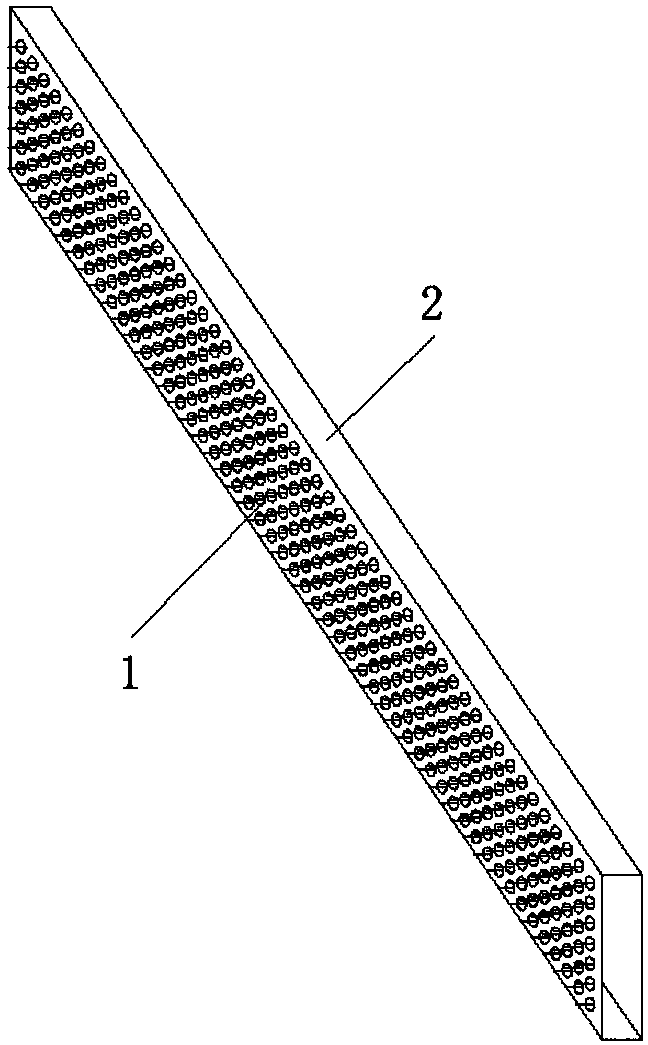
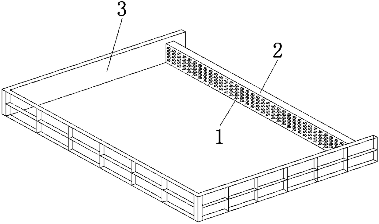
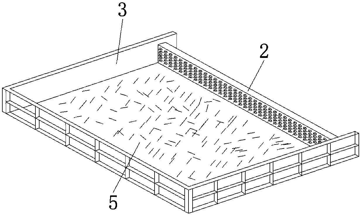
[0030] Example 1, such as Figure 1-7 As shown in one of the above, the fiber-continuous construction method of the concrete structure joint of the present invention is to arrange the fine holes according to the design interval on the formwork of the concrete joint 4 (the formwork of the joint 4 is a steel formwork 2) before pouring. After the concrete pouring is completed and before the initial setting of the concrete 5 near the joint, part of the length of the fiber 1 is inserted into the uncured concrete 5 through the fine hole, and after the concrete 5 is hardened and the steel formwork 2 at the joint 4 is removed, Outside the surface of the joint 4 of the concrete 5, the remaining part of the length not inserted into the concrete 5 is exposed. The fibers 1 at the joints 4 of the poured concrete 5 and 6 are continuous.

[0031] In Example 1, the pore diameter is larger than the fiber 1 diameter, and the pore diameter is less than 2 mm. The fine holes on the steel formwor...


PUM

PropertyMeasurementUnit
Pore diameteraaaaaaaaaa

Abstract

The invention discloses a continuous construction method for fibers at a joint of a concrete structure. The continuous construction method comprises the steps that thin holes are formed at designed intervals in a formwork at a joint of first-poured concrete, the fibers with certain lengths are inserted into unset concrete through the thin holes after the first-poured concrete is poured and beforethe concrete near the joint is initially set, and after the concrete is hardened and the formwork at the joint is removed, the remaining fibers, with certain lengths, which are not inserted into the concrete are exposed outside the surface of the concrete joint; and when concrete on the other side of the joint is poured again, the fibers are connected between the concrete which is poured by two times to enable the fibers to be continuous at the joint of the concrete which is poured separately. The continuous construction method for the fibers at the joint of the concrete structure fundamentally solves the problem of discontinuity of fibers at the joint of the concrete structure, and it is not necessary to improve joint performance by the complex joint forms such as changing the joint shape, densifying reinforcements or adopting a special-shaped steel plate. The continuous construction method for fibers at the joint of the concrete structure has low engineering cost, convenient construction, material saving, excellent structure performance, and good prospect of popularization.

Description

technical field [0001] The invention relates to the technical field of civil engineering, in particular to a continuous fiber construction method at joints of concrete structures. Background technique [0002] Concrete with fibers (ordinary fiber concrete, ultra-high performance concrete, etc.) is widely used in the field of civil engineering due to its excellent mechanical properties. The fibers in the concrete matrix with fibers can retard the development of concrete cracks, thereby increasing its tensile, bending, and shear strength, and its impact resistance, fatigue resistance, post-crack toughness, and durability are also greatly improved. Whether it is a prefabricated structure or a staged pouring structure, it is difficult to avoid the existence of joints (including construction joints, boundary joints, etc.), which also involves the connection of old and new concrete interfaces. Especially for concrete structures with fibers, the existence of joints will lead to fi...

Claims


Application Information

Patent Timeline
IPC IPC(8): E04B1/68E04G21/02
CPCE04B1/68E04G21/02
Inventor 赵秋杨建平
Owner FUZHOU UNIVERSITY
Learn More