
Seam for multiaxial papermaking fabrics

a multi-axle, fabric technology, applied in the field of multi-axle seams, can solve the problems of seam area, fabric wear and replacement, and difficulty in streamlined manufacturing process, and achieve the effect of improving the seam area of multi-axle fabrics

Active Publication Date: 2008-06-03
ALBANY INT CORP
View PDF16 Cites 1 Cited by
  • Summary
  • Abstract
  • Description
  • Claims
  • Application Information

AI Technical Summary

Benefits of technology

The present invention provides an improved seam for multiaxial fabrics, which solves the problem of yarn migration in the seam area. The seam provides uniform support for the fiber batting material in the seam area. The method involves removing yarns in the cross-machine direction (CD) from the edges of ravel areas to create ravel areas, which are then affixed with CD materials to bind the body yarn segments along the CD edges of the ravel areas. The fabric is seamed by interdigitating the seam loops from the ravel areas and inserting a pintle therthrough. The method may further include reweaving additional CD yarns into the ravel areas to impart desired characteristics to the seam area. The fabric is formed of a woven fabric strip having a width that is less than a width of the fabric, the fabric strip being in the form of a multi-layer weave with two lateral edges to form a spiral seam. The fabric may include an on-machine-seamable multiaxial press fabric for the press section of a paper machine, with at least one layer of staple fiber batting material needled into the fabric. The yarns may have a circular cross-sectional shape, a rectangular cross-sectional shape or a non-round cross-sectional shape.

Problems solved by technology

Needless to say, this requirement makes it difficult to streamline the manufacturing process, as each press fabric must typically be made to order.
These fabrics wear out and require replacement.
As such, their use had been limited to press sections having cantilevered press rolls and other components, which permit an endless press fabric to be installed from the side of the press section.
A drawback to this approach of creating a seam in the multiaxial fabric structure is the CD yarn tails that result in the seam area.
In addition, these unbound yarns do not provide suitable uniform support for the fiber batting material in the seam area.
Attempts have been made to use certain adhesives to bind these yarns and prevent migration, but with limited success.

Method used


Image

  • Seam for multiaxial papermaking fabrics
  • Seam for multiaxial papermaking fabrics
  • Seam for multiaxial papermaking fabrics

Examples


Embodiment Construction

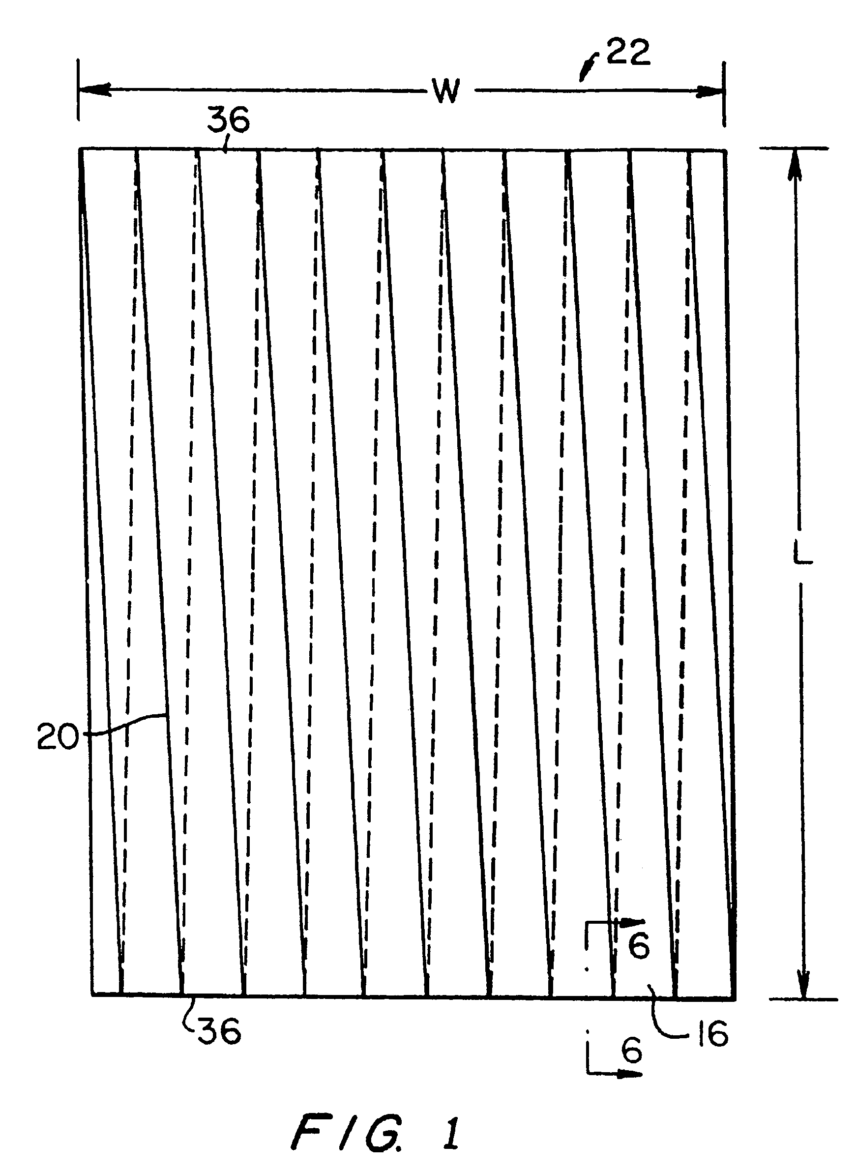
[0062]The preferred embodiments of the present invention will now be described by reference to FIG. 1. FIG. 1 is a top plan view of a multiaxial base fabric in a flattened condition. Once the base fabric 22 has been assembled, as taught in commonly assigned U.S. Pat. Nos. 5,916,421; 5,939,176; and 6,117,274 to Yook described hereinabove, it is flattened as shown in the plan view presented in FIG. 1. This places base fabric layer 22 into the form of a two-ply fabric of length, L, which is equal to one half of the total length, C, of the base fabric layer 22 and width, W. Seam 20 between adjacent turns of woven fabric strip 16 slants in one direction in the topmost of the two plies, and in the opposite direction in the bottom ply, as suggested by the dashed lines in FIG. 1. Flattened base fabric layer 22 has two widthwise edges 36.

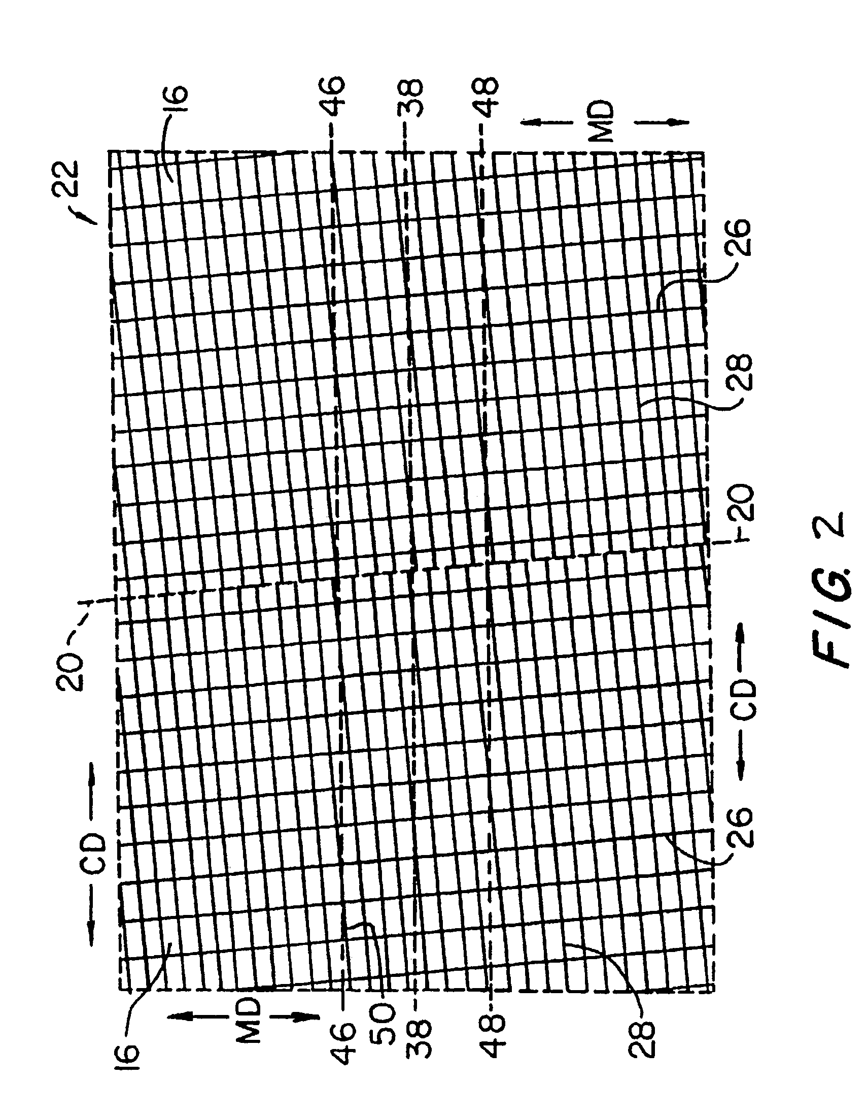
[0063]FIG. 3 is a schematic cross-sectional view taken as indicated by line 6-6 in FIG. 1. In accordance with the present invention, a plurality of crosswis...


PUM

PropertyMeasurementUnit
lengthaaaaaaaaaa
lengthaaaaaaaaaa
angleaaaaaaaaaa

Abstract

A method of seaming an on-machine-seamable multiaxial papermaker's fabric to prevent yarn migration. The multiaxial fabric is in the form of an endless loop flattened into two layers along fold lines. CD yarns are removed from the folds to create extended ravel areas. This leaves the MD yarns unbound in the ravel areas. Seam loops are then formed from the unbound MD yarns at the folds. CD materials (e.g. continuous CD yarns) are affixed to (rewoven into) the fabric along the edges of the ravel area at each fold. The affixed CD materials bind the CD yarn tails along the edges of the ravel areas to prevent migration of CD yarn tails into the seam area.

Description

BACKGROUND OF THE INVENTION[0001]1. Field of the Invention[0002]The present invention relates to the seaming of multiaxial fabrics on a papermaking machine.[0003]2. Description of the Prior Art[0004]During the papermaking process, a cellulosic fibrous web is formed by depositing a fibrous slurry, that is, an aqueous dispersion of cellulose fibers, onto a moving forming fabric in the forming section of a paper machine. A large amount of water is drained from the slurry through the forming fabric, leaving the cellulosic fibrous web on the surface of the forming fabric.[0005]The newly formed cellulosic fibrous web proceeds from the forming section to a press section, which includes a series of press nips. The cellulosic fibrous web passes through the press nips supported by a press fabric, or, as is often the case, between two such press fabrics. In the press nips, the cellulosic fibrous web is subjected to compressive forces which squeeze water therefrom, and which adhere the cellulos...

Claims


Application Information

Patent Timeline
Patent Type & Authority Patents(United States)
IPC IPC(8): D21F7/10B32B5/24D21F7/12D03D3/02D21F1/10D21F1/00
CPCD21F1/0054D21F7/10Y10S162/903Y10T428/19Y10S162/90Y10S162/904Y10S162/902
Inventor KORNETT, GLENNRYDIN, BJORNJONASSON, BODILRAE, SANDRAOXLEY, FRANKKREBS, DAVE
Owner ALBANY INT CORP
Learn More