Dehumidification method for main cable of suspension bridge

A suspension bridge and main cable technology, applied in the direction of suspension bridges, bridges, bridge forms, etc., can solve the problems of large gas flow resistance, narrow wire gap, and high cost, and achieve the effect of reducing resistance, reducing electricity costs, and simplifying the dehumidification system.

Active Publication Date: 2020-11-17
ZHENGZHOU UNIV
View PDF10 Cites 5 Cited by
  • Summary
  • Abstract
  • Description
  • Claims
  • Application Information

AI Technical Summary

Problems solved by technology

Due to the narrow space between the steel wires of the main cable and the large gas flow resistance, the whole bridge needs multiple sets of dehumidification equipment, which consumes a lot of power and costs high

Method used


Image

  • Dehumidification method for main cable of suspension bridge
  • Dehumidification method for main cable of suspension bridge
  • Dehumidification method for main cable of suspension bridge

Examples


Embodiment 1

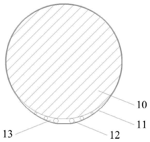
[0044] What is shown in this embodiment is that the main cable has a cavity at the bottom, and there is a connecting pipe connecting two adjacent cavities across the cable clamp to form a bottom airflow channel. see figure 1 — Figure 7 ,and Figure 14 .figure 1 The cross-sectional schematic diagram of the main cable, the steel wire bundle 10 of the main cable is wound with round steel wires on the surface after the cable is tightened. The transparent stainless steel pipe 12 forms a supporting member, which clings to the steel wire at the bottom of the steel wire bundle 10 , and then wraps the wrapping tape 11 to form a cavity 13 at the bottom. The schematic diagram of transparent stainless steel pipe 12 is shown in Figure 5 , there are holes 15 on the pipe wall, the diameter of the holes 15 is equal to the radius of the transparent stainless steel pipe 12, the longitudinal spacing of the holes 15 is the diameter of the transparent stainless steel pipe 12, these holes 15 a...

Embodiment 2

[0048] This embodiment is a modification of Embodiment 1, the connecting pipe 14 is removed, and the installation work and maintenance work of the connecting pipe 14 are avoided. See Figure 8 and Figure 9 . The schematic diagram of the left end face of the cable clamp is shown in Figure 8 , in order to ensure that the bottom cavities 13 on both sides of the cable clamp are connected, a longitudinal through hole 19 is added in the cable clamp. See Figure 9 , The appearance of the main cable is simple, the airflow channel at the bottom is smoother, and the resistance is smaller.

Embodiment 3

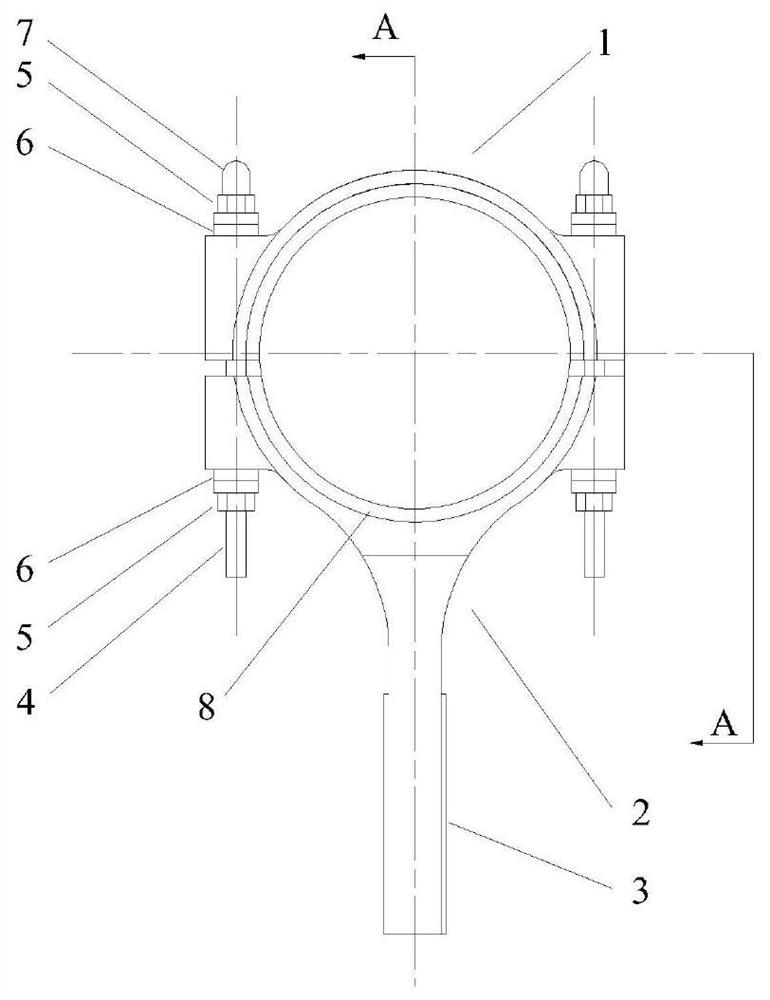
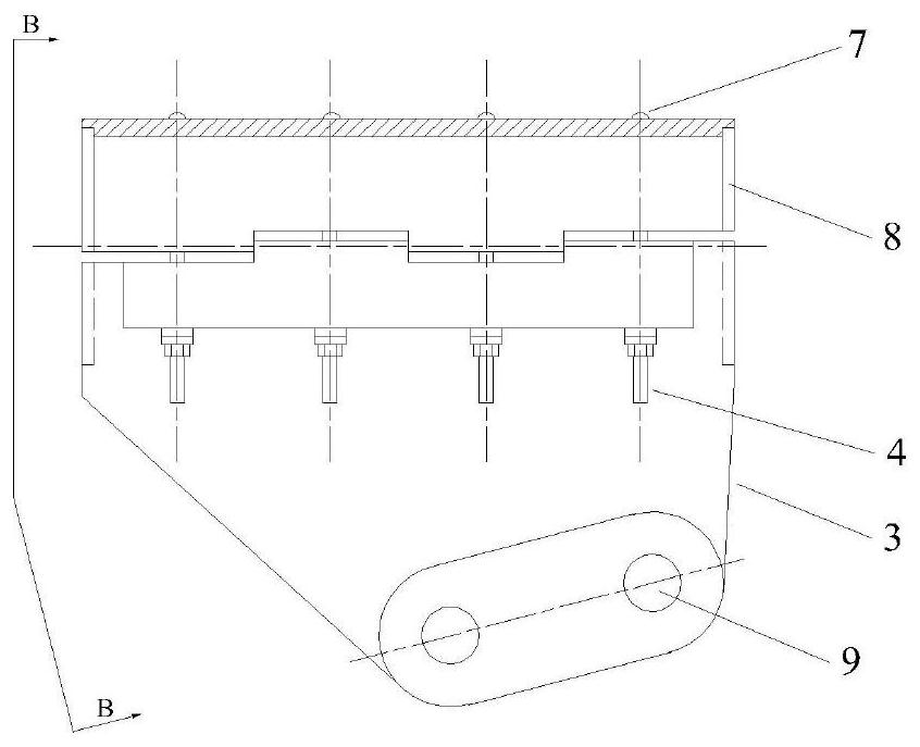
[0050] This embodiment is a kind of improved form of embodiment 2, and the top of main cable has increased cavity, see Figure 10 A cross-sectional schematic diagram of the main cable, the main cable has a bottom cavity 13 and a top cavity 20, and the top cavity 20 has a cavity support member composed of transparent stainless steel pipes 12. Figure 11 It is a schematic diagram of the left end face of the cable clamp, considering that the end slot 8 in the conventional cable clamp has no practical value in this program and has been cancelled. Figure 12 It is a schematic diagram of the connection between the two ends of the cable clamp and the wrapping belt 11. For the convenience of the top cavity 20 to form the top air flow channel, the cavity at the two ends of the cable clamp is communicated with the connecting pipe 14. There is an air valve 28 at the farthest end of the top air flow passage from the corresponding blower, see Figure 16 ; During the day, after the humidit...


PUM


Abstract

The invention discloses a dehumidification method for a main cable of a suspension bridge. The surface of the main cable is sealed and wrapped by the wrapping tape, and the wrapping tape and the internal main cable steel wires form cavities at the top and the bottom, thereby facilitating the flowing of dry gas. The principle that moisture in the main cable circularly rises and falls day and nightis ingeniously utilized, and when the moisture is gathered in the cavity, dry gas is introduced to discharge the moisture. Dry gas flow resistance is small, required operation time is short, energy consumption is low, an air feeder does not need to be installed on the upper portion of the bridge tower, and investment is saved; moreover, dry gas can flow at low pressure, the wrapping tape is not easy to break, a special gas inlet cable clamp, a special gas outlet cable clamp and a corresponding pipeline system are not required to be mounted, high-altitude operation in system maintenance is reduced, and the maintenance cost is reduced.

Description

technical field [0001] The invention relates to the anticorrosion of the steel wire of the main cable of the suspension bridge in bridge engineering, in particular to a dehumidification method for the main cable of the suspension bridge. Background technique [0002] The main cable is one of the most important stress-bearing components of the suspension bridge, known as the "lifeline". It has been exposed to the atmospheric environment for a long time and is subjected to erosion by various adverse environments. At the same time, since the main cable is a non-replaceable component, the service life of the main cable directly affects the service life of the suspension bridge. [0003] The usual main cable protection system is to apply a layer of protective putty on the surface of the main cable, such as red lead or zinc powder paste, wrap the outside with round galvanized soft steel wire, and then carry out anti-corrosion coating on the outer surface of the wrapped steel wire ...

Claims


Application Information

Patent Timeline
Patent Type & Authority Applications(China)
IPC IPC(8): E01D19/16E01D11/02E01D22/00F26B21/00
CPCE01D19/16E01D11/02E01D22/00F26B21/004
Inventor 魏建东郝放戚丹丹陈家模齐清华宋博
Owner ZHENGZHOU UNIV
Why Eureka
Try Eureka