A kind of dehumidification method of suspension bridge main cable
A technology for suspension bridges and main cables, applied to suspension bridges, bridges, bridge parts, etc., can solve the problems of large gas flow resistance, narrow steel wire gaps, and high costs, and achieve the effects of reducing air flow resistance, less power consumption, and low air pressure
- Summary
- Abstract
- Description
- Claims
- Application Information
AI Technical Summary
Problems solved by technology
Method used
Image
Examples
Embodiment 1
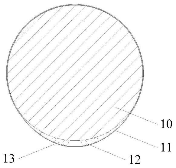
[0044] This embodiment shows the case where the main cable has a bottom cavity, and a communication pipe connects the two adjacent cavities across the cable clip to form a bottom airflow channel. see figure 1 — Figure 7 ,and Figure 14 .figure 1 A schematic diagram of the cross-section of the main cable, the surface of the wire bundle 10 of the main cable is wound with round steel wires after the cable is tightened. The transparent stainless steel tube 12 forms a support member, which is closely attached to the steel wire at the bottom of the steel wire bundle 10, and then wound with the wrapping tape 11, thereby forming the bottom cavity 13. See the schematic diagram of the transparent stainless steel pipe 12 Figure 5 , there are holes 15 on the pipe wall, the diameter of the holes 15 is equal to the radius of the transparent stainless steel pipe 12, the longitudinal spacing of the holes 15 is the diameter of the transparent stainless steel pipe 12, these holes 15 are sp...
Embodiment 2
[0048] This embodiment is a modification of the first embodiment, and the communication pipe 14 is removed, which avoids the installation work and maintenance work of the communication pipe 14. See Figure 8 and Figure 9 . The schematic diagram of the left end face of the cable clamp is shown in Figure 8 , in order to ensure the communication between the bottom cavities 13 on both sides of the cable clip, longitudinal through holes 19 are added in the cable clip. The schematic diagram of the connection between the two ends of the cable clip and the wrapping tape 11 is shown in Figure 9 , The appearance of the main cable is simple, the bottom airflow channel is smoother, and the resistance is smaller.
Embodiment 3
[0050] This embodiment is an improved form of Embodiment 2, and a cavity is added to the top of the main cable, see Figure 10 A schematic cross-sectional view of the main cable, the main cable has a bottom cavity 13 and a top cavity 20, and the top cavity 20 has a cavity support composed of a transparent stainless steel tube 12. Figure 11 It is a schematic diagram of the left end face of the cable clip, considering that the end slot 8 in the conventional cable clip has no practical value in this solution and has been cancelled. Figure 12 It is a schematic diagram of the connection between the two ends of the cable clip and the wrapping tape 11. In order to facilitate the top cavity 20 to form a top airflow channel, a communication pipe 14 is used to communicate the cavities at both ends of the cable clip. The top airflow channel has an air valve 28 at the farthest end of the corresponding blower, see Figure 16 ; In the daytime, when the humidity in the top airflow channel...
PUM
 Abstract
Description
Claims
Application Information
 - R&D
- Intellectual Property
- Life Sciences
- Materials
- Tech Scout
- Unparalleled Data Quality
- Higher Quality Content
- 60% Fewer Hallucinations
Browse by: Latest US Patents, China's latest patents, Technical Efficacy Thesaurus, Application Domain, Technology Topic, Popular Technical Reports.
© 2025 PatSnap. All rights reserved.Legal|Privacy policy|Modern Slavery Act Transparency Statement|Sitemap|About US| Contact US: help@patsnap.com


