Refrigeration cycle system and control method thereof
A technology of circulation system and pipeline, applied in the field of refrigeration circulation system and its control, can solve problems such as refrigeration interruption, and achieve the effect of ensuring safe operation
- Summary
- Abstract
- Description
- Claims
- Application Information
AI Technical Summary
Problems solved by technology
Method used
Image

Examples
Embodiment 1
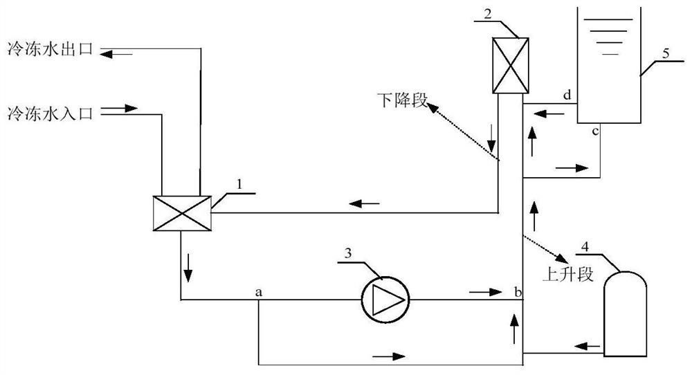
[0091] This embodiment provides a refrigeration cycle system, figure 1 It is a structural diagram of the refrigeration cycle system according to the first embodiment of the present invention, such as figure 1 As shown, the refrigeration cycle system includes: a first heat exchanger 1, the water side of the first heat exchanger 1 is respectively connected to the chilled water inlet and the chilled water outlet, so that the water entering through the chilled water inlet is cooled and then flows out from the chilled water outlet ; Also include the first pipeline communicated between the outlet end of the first heat exchanger 1 and the inlet end of the second heat exchanger 2, the first pipeline is provided with a liquid pump 3; the outlet end of the first heat exchanger 1 There is also a second pipeline between the inlet end of the second heat exchanger 2, the first end a and the second end b of the second pipeline are connected with the first pipeline, and the first end a and th...
Embodiment 2
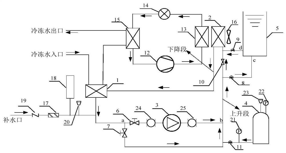
[0097] This embodiment provides another refrigeration cycle system, figure 2 It is a structural schematic diagram of the refrigeration cycle system according to the second embodiment of the present invention, in order to realize the flow direction control of the heat exchange medium, such as figure 2 As shown, the system also includes: a first valve 6, arranged on the first pipeline, between the liquid pump 3 and the first end a of the second pipeline, for controlling whether the heat exchange medium flows into the liquid pump 3. When the system is powered on normally, the first valve 6 is opened to prevent the heat exchange medium from flowing into the liquid pump 3. When the system is powered off, the first valve 6 is closed so that the heat exchange medium does not flow into the liquid pump 3.
[0098] The system also includes a second valve 7, which is set on the second pipeline and is used to control whether the second pipeline is conducted, that is, to control whether ...
Embodiment 3
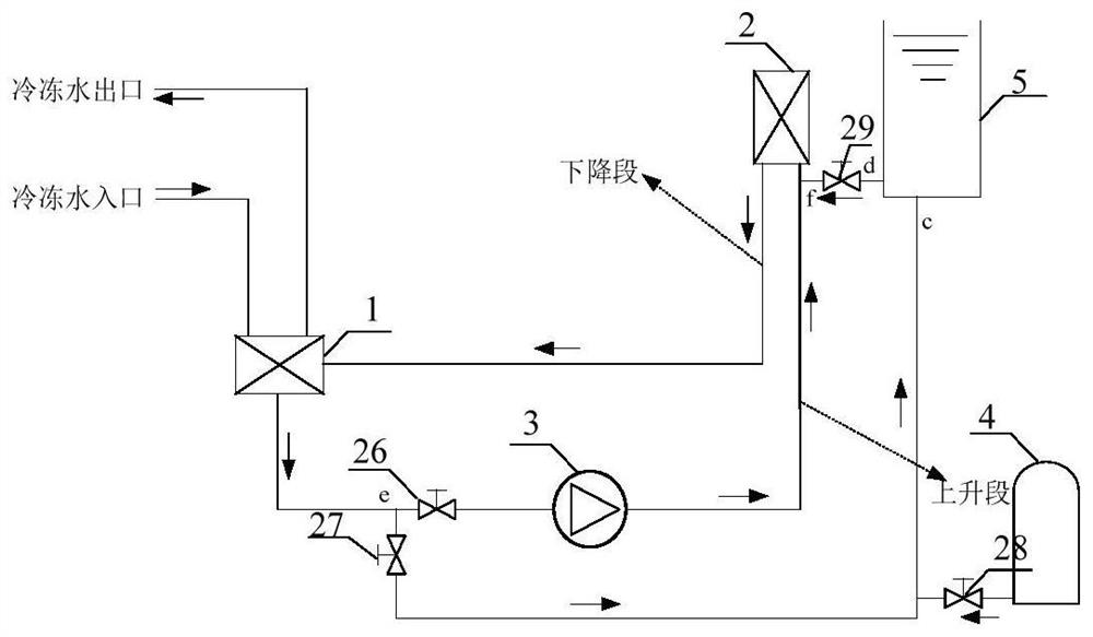
[0113] This embodiment provides another refrigeration cycle system, image 3 It is a structural diagram of a refrigeration cycle system according to a third embodiment of the present invention, such as image 3 As shown, the system includes: a third pipeline connected between the first heat exchanger 1 and the second heat exchanger 2, and a liquid pump 3 is arranged on the third pipeline; a fourth pipeline, the first Both the end e and the second end f are connected with the third pipeline, and the first end e and the second end f are located on both sides of the liquid pump 3; the high-pressure gas storage tank 4 is arranged on the The fourth pipeline is used to discharge high-pressure gas to drive the circulation of the heat exchange medium; the liquid storage tank 5 is arranged on the fourth pipeline, between the high-pressure gas storage tank 4 and the second heat exchanger 2, and The inlet port c is connected to the high-pressure gas storage tank 4, and the outlet port d...
PUM
 Abstract
Description
Claims
Application Information
 - Generate Ideas
- Intellectual Property
- Life Sciences
- Materials
- Tech Scout
- Unparalleled Data Quality
- Higher Quality Content
- 60% Fewer Hallucinations
Browse by: Latest US Patents, China's latest patents, Technical Efficacy Thesaurus, Application Domain, Technology Topic, Popular Technical Reports.
© 2025 PatSnap. All rights reserved.Legal|Privacy policy|Modern Slavery Act Transparency Statement|Sitemap|About US| Contact US: help@patsnap.com