Refrigerator

A refrigerator and box body technology, applied in the field of refrigerators, can solve the problems of reducing the cooling capacity of the refrigerating evaporator, uneven temperature distribution in the refrigerating room, and the cooling capacity cannot be used by the compartment, so as to improve the space utilization rate and shorten the air supply distance. , The effect of preventing the wind from the fins

Active Publication Date: 2020-11-17
QINGDAO HAIER REFRIGERATOR CO LTD +1
View PDF6 Cites 0 Cited by
  • Summary
  • Abstract
  • Description
  • Claims
  • Application Information

AI Technical Summary

Problems solved by technology

At the same time, in order to make the defrosting water flow out smoothly, the water receiving tray is usually designed as a funnel, and the existing refrigerators do not use this part of the space, losing the effective volume
In addition, the evaporator in the refrigerating room mostly adopts a multi-row parallel structure, which is installed at the rear of the refrigerating room, and the fan is placed on the upper end of the refrigerating evaporator. This design mode has certain shortcomings, such as the thickness of the multi-row refrigerating evaporator is large, The depth of the compartment is reduced, and the usable space is reduced. The fan is installed at the upper end of the refrigeration evaporator. After the cooled air passes through the fan, it needs to pass through a long air duct to enter the compartment to exert the cooling effect. The loss in the air duct Most of the cold energy cannot be used by the compartment, which reduces the cooling capacity of the refrigerating evaporator and causes uneven temperature distribution in the refrigerating room

Method used


Image

  • Refrigerator
  • Refrigerator
  • Refrigerator

Examples


Embodiment Construction

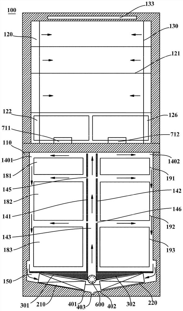
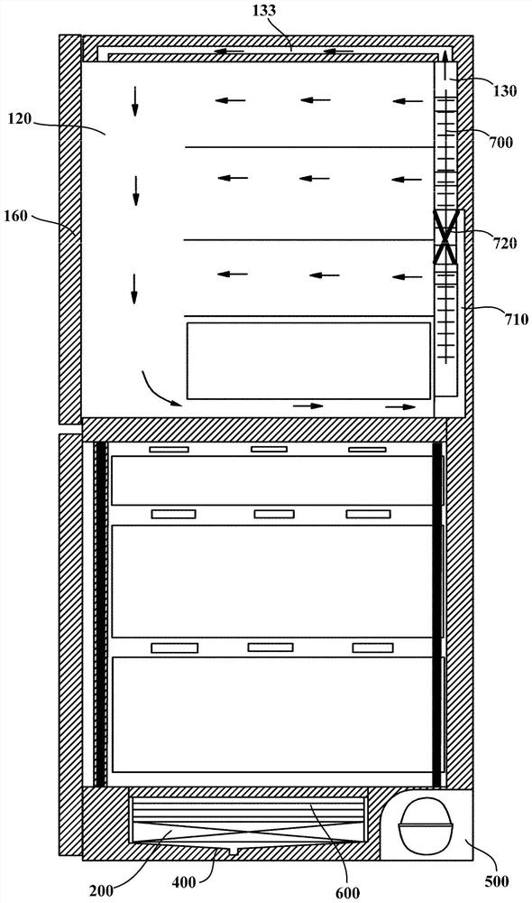
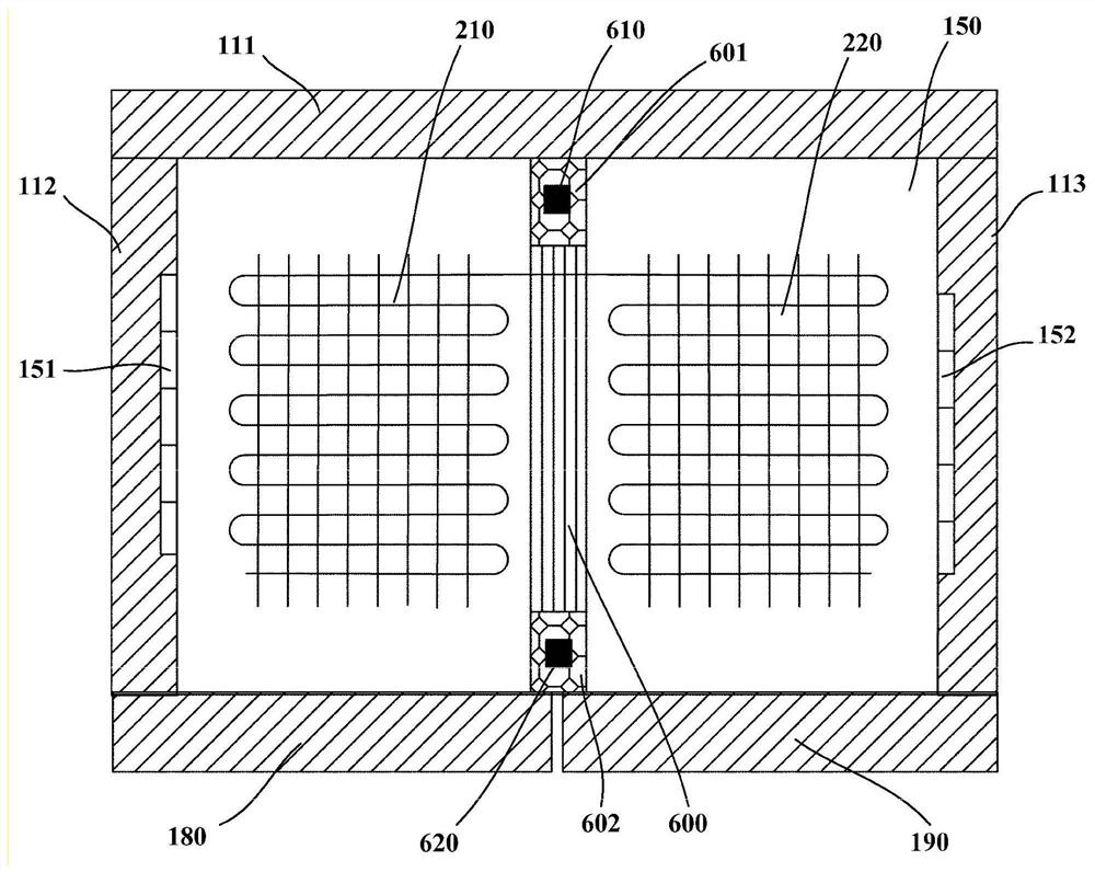
[0053] figure 1 is a front schematic sectional view of a refrigerator 100 according to an embodiment of the present invention. figure 2 is a side schematic sectional view of a refrigerator 100 according to an embodiment of the present invention. image 3 yes figure 1 A schematic top view of the first evaporator 200 of the refrigerator 100 is shown. In the following description, orientations or positional relationships indicated by "front", "rear", "upper", "lower", "left", "right", etc. are orientations based on the refrigerator 100 itself as a reference.

[0054] The refrigerator 100 of the embodiment of the present invention may generally include a box body 110. The box body 110 includes an outer shell and a storage liner arranged inside the outer shell. The space between the outer shell and the storage liner is filled with thermal insulation material (forming a Bubble layer), the storage liner is defined with a storage compartment. In one embodiment, the storage compar...


PUM


Abstract

The invention provides a refrigerator which comprises a refrigerator body, a first evaporator and a second evaporator. A first cooling chamber, a second cooling chamber, a first storage chamber, a second storage chamber, a third storage chamber and an air return duct are limited in the refrigerator body. The first storage chamber and the second storage chamber are arranged above the first coolingchamber in parallel at an interval; the second cooling chamber is arranged at the rear part of the third storage chamber; the first evaporator is arranged in the first cooling chamber; the second evaporator is arranged in the second cooling chamber; at least one first air return port communicated with the first cooling chamber is formed in the left side wall of the first storage chamber; at leastone second air return port communicated with the first cooling chamber is formed in the right side wall of the second storage chamber; a third air return port communicated with the third storage chamber is formed in the rear surface of the second cooling chamber, and the air return duct communicates with the third storage chamber and the third air return port. The effective volume of the chambersis increased, so that return air flow of the storage chambers enters the cooling chambers through the air return ports to be cooled, and drawer avoiding in the chambers is not needed.

Description

technical field [0001] The invention relates to the technical field of refrigeration and freezing devices, in particular to a refrigerator. Background technique [0002] The refrigerating air duct of traditional side-by-side refrigerators is usually placed on the rear side wall. Since the air duct composed of the first evaporator itself, the air supply fan, and the front and rear cover plates of the air duct is relatively thick, it occupies the space at the rear of the compartment, resulting in The usable volume is greatly reduced. At the same time, the cold air is sent to the storage compartment through the air supply fan. Due to the large space of the freezer compartment, the air volume transmission path is long and the cooling capacity loss is large. The farther away from the air outlet, the smaller the air volume. At the same time, in order to allow the defrosting water to flow out smoothly, the water receiving tray is usually designed as a funnel, and the existing refr...

Claims


Application Information

Patent Timeline
Patent Type & Authority Applications(China)
IPC IPC(8): F25D11/02F25D17/08F25D25/02
CPCF25D11/02F25D17/08F25D25/025
Inventor 刘山山曹东强李伟
Owner QINGDAO HAIER REFRIGERATOR CO LTD
Why Eureka
Try Eureka