
A high-efficiency and high-speed analytical countercurrent chromatograph

A countercurrent chromatograph, analytical technology, applied in the field of high-efficiency and high-speed analytical countercurrent chromatograph, can solve problems such as unsuitable operation, poor stability, poor equipment stability, etc.

Active Publication Date: 2021-04-16
SICHUAN UNIV
View PDF10 Cites 0 Cited by
  • Summary
  • Abstract
  • Description
  • Claims
  • Application Information

AI Technical Summary

Problems solved by technology

However, due to the unwinding of the flyleads unwinding tube used in the prior art countercurrent chromatograph, it is prone to fatigue damage at a slightly high speed (over 2500r / min), which in turn leads to the interruption of the entire countercurrent chromatographic process, and the separation cannot be achieved. However, the countercurrent chromatograph of the prior art cannot achieve ultra-high speed separation
At the same time, the countercurrent chromatograph in the prior art is limited by the structure of the flyleads unwinding tube, so it can only be set up with a cantilever structure; especially at ultra-high speeds, the position of the center of gravity of the flyleads unwinding tube will vary with the rotation process. Changes make it difficult to guarantee the overall dynamic balance, poor stability and low reliability during equipment operation
In addition, in some experimental environments, in addition to requiring the chromatograph to meet the ultra-high-speed separation capability, there are also certain requirements for the amount of sample separation. However, the countercurrent chromatograph in the prior art can only use A single separation column (if two separation columns are used at the same time, the flyleads unwinding tubes from the two separation columns will interfere with each other under high-speed operation), to meet the requirements of experimental analysis can only be achieved by increasing the capacity of the separation column, which In turn, the volume of the equipment will become larger, which is not suitable for the operation and use in the laboratory environment. At the same time, the dynamic balance of the equipment is not easy to ensure after the volume becomes large, and the stability of the equipment is poor.

Method used


Image

  • A high-efficiency and high-speed analytical countercurrent chromatograph
  • A high-efficiency and high-speed analytical countercurrent chromatograph
  • A high-efficiency and high-speed analytical countercurrent chromatograph

Examples


Embodiment Construction

[0035] The technical solution of the present invention will be further described in detail below in conjunction with the accompanying drawings, but the protection scope of the present invention is not limited to the following description.

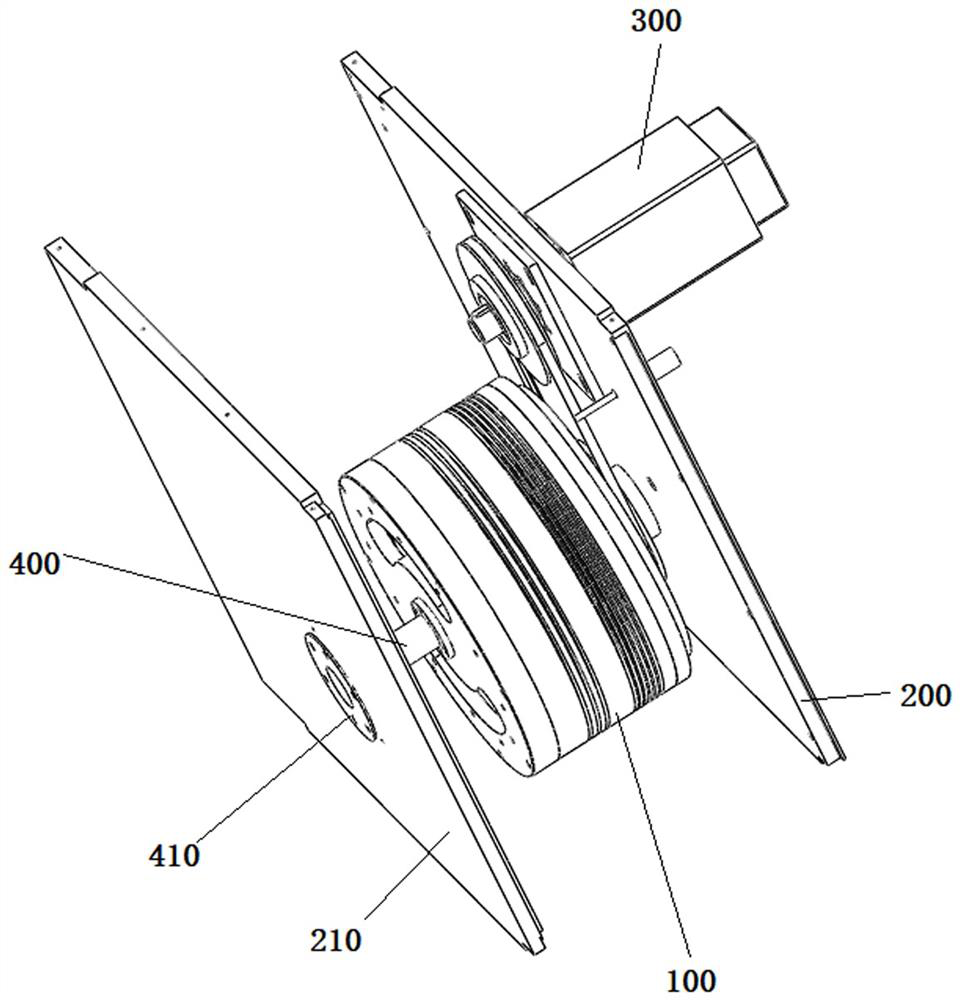
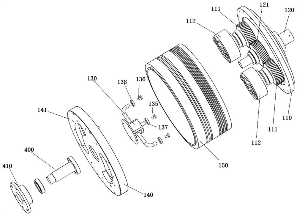
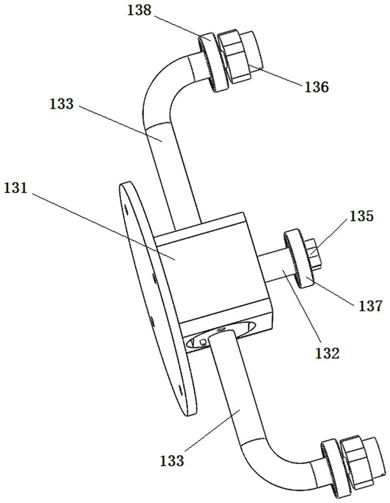
[0036] Such as Figure 1 to Figure 5As shown, a high-efficiency and high-speed analytical countercurrent chromatograph is improved on the basis of the structure of the planetary countercurrent chromatograph in the prior art, so as to meet the ultra-high speed separation requirements of the analytical countercurrent chromatograph in the laboratory environment.

[0037] The countercurrent chromatograph in the prior art includes a rotor mechanism 100, a first support plate 200, and a driving mechanism 300. The rotor mechanism 100 includes a planet carrier 110 and a hollow central shaft 120. The driving mechanism 300 and the central shaft 120 are fixedly arranged on the first On the supporting board 200 , the driving mechanism 300 is used to dr...


PUM


Abstract

The invention discloses a high-efficiency and high-speed analytical countercurrent chromatograph, which is provided with a metal unwinding frame and a dynamic balance adjustment plate on the existing chromatograph; the metal unwinding frame includes a metal seat, a metal straight pipe, a central shaft oil plug, Two symmetrically arranged metal elbows and two separation column oil plugs, one end of the metal elbow is fixedly connected with the metal base, one end of the separation column oil plug is tightly connected with the center hole of the separation column, and the other end of the separation column oil plug Set in the other end of the metal elbow, one end of the metal straight pipe is fixedly connected with the metal seat, one end of the central shaft oil plug is tightly connected with one end of the central shaft, and the other end of the central shaft oil plug is set on the other end of the metal straight pipe In one end, the metal straight pipe and the two metal bent pipes are connected, and the metal straight pipe and the two metal bent pipes are provided with inner hoses filled with grease; the metal seat and the planet carrier are connected through a dynamic balance adjustment plate. The chromatograph can realize countercurrent chromatographic separation at ultra-high speed, and at the same time meet the characteristics of small size and high reliability.

Description

technical field [0001] The invention relates to the technical field of an analytical countercurrent chromatograph, in particular to an efficient and high-speed analytical countercurrent chromatograph. Background technique [0002] Countercurrent chromatography technology is a continuous and efficient liquid-liquid partition chromatography separation technology developed in the 1970s. It generates a two-dimensional force field through synchronous planetary motion of simultaneous revolution and rotation, and retains one of the two phases. As a stationary phase, separation and extraction are achieved during high-speed rotation. [0003] Since the countercurrent chromatography technology needs to generate a two-dimensional force field that revolves and rotates simultaneously, the countercurrent chromatographs in the prior art often use a planetary gear mechanism as the main structure (such as the structure disclosed in PCT patent WO03 / 086639A2). The structure includes a support...

Claims


Application Information

Patent Timeline
Patent Type & Authority Patents(China)
IPC IPC(8): G01N30/02G01N30/60G01N30/46
CPCG01N30/02G01N30/46G01N30/60
Inventor 殷国富陈海军黄河来刘海淞彭爱华吴宇轩陈俐娟
Owner SICHUAN UNIV
Learn More