Unmanned aerial vehicle video relay system and method for minimizing energy consumption thereof

A relay system, UAV technology, applied in the direction of radio transmission system, transmission system, reducing energy consumption, etc., can solve problems such as increasing the energy consumption of UAVs and increasing the flight distance of UAVs

Active Publication Date: 2020-11-17
SOUTHWEST UNIV
View PDF4 Cites 17 Cited by
  • Summary
  • Abstract
  • Description
  • Claims
  • Application Information

AI Technical Summary

Problems solved by technology

However, such a flight trajectory will result in a longer flight distance of the UAV, which will increase the energy consumption of the UAV in general

Method used


Image

  • Unmanned aerial vehicle video relay system and method for minimizing energy consumption thereof
  • Unmanned aerial vehicle video relay system and method for minimizing energy consumption thereof
  • Unmanned aerial vehicle video relay system and method for minimizing energy consumption thereof

Examples


Embodiment 1

[0111] 1. System model

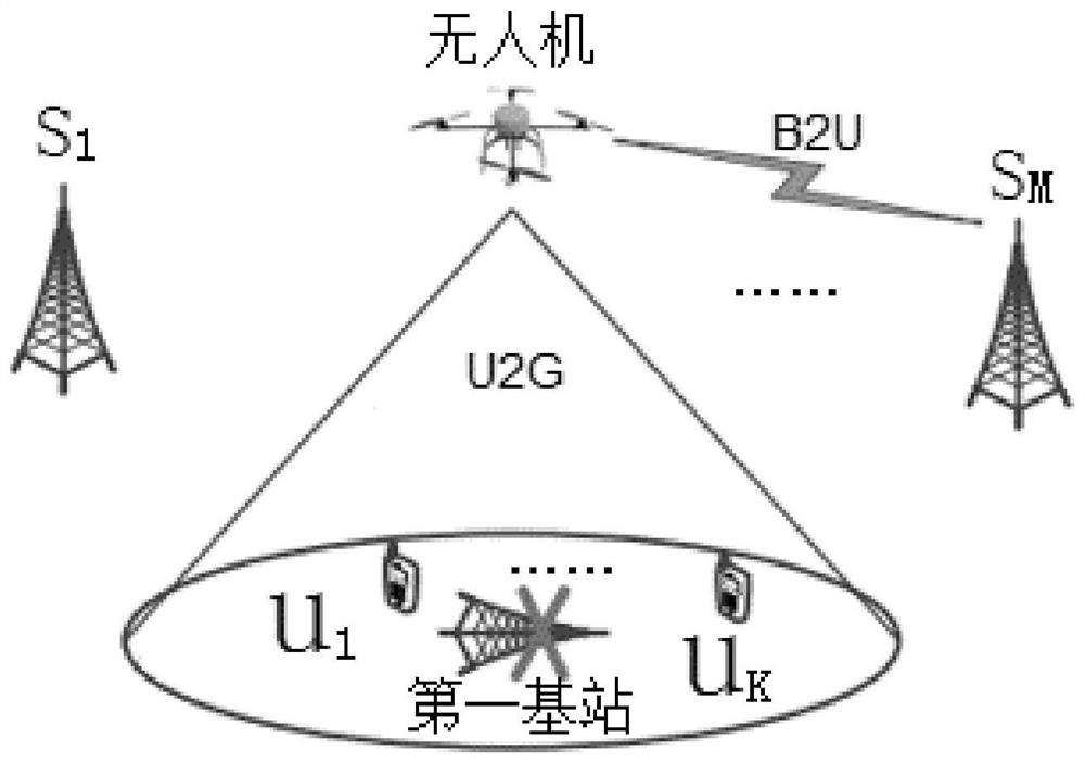
[0112] An embodiment of the present invention provides an unmanned aerial vehicle video relay system, such as figure 1 The system structure diagram shown includes the first base station which does not work, and K users U={u in the coverage area of ​​the first base station 1 ,u 2 … u K}, and M normal working second base stations adjacent to the first base station S={s 1 ,s 2 …s M}, and the UAV deployed between the second base station and the user for video relay, K≥2, M≥2.

[0113] In this system, the established first base station is out of service (eg due to damage or maintenance). Such an area may be a remote area where there is no direct connection between other base stations (second base stations) and users. In this case, drones are deployed as a quick solution for wireless access services. Since the rotary-wing drone has the ability to hover over users to provide better video services, the rotary-wing drone is adopted as an aerial relay pl...

Embodiment 2

[0151] Based on the UAV video relay system of Embodiment 1, this embodiment designs a method for minimizing energy consumption of the UAV video relay system, including steps:

[0152] S1. Construct the energy consumption minimization constraint model of the UAV video relay system;

[0153] S2. Decomposing the energy consumption minimization constraint model into a transmission power and bandwidth optimization sub-model, and a UAV trajectory optimization sub-model;

[0154] S3. Using successive convex approximation and alternate optimization methods to solve the transmission power and bandwidth optimization sub-model and the UAV trajectory optimization sub-model, obtain a suboptimal solution satisfying the Karush-Kuhn-Tucker condition as the energy consumption minimization Optimal solution to a constrained model.

[0155] 1. Energy consumption minimization constraint model

[0156] This embodiment aims to minimize the total energy consumption of the UAV in consecutive T time ...


PUM


Abstract

The invention relates to the technical field of unmanned aerial vehicle video relay, and particularly discloses an unmanned aerial vehicle video relay system and an energy consumption minimization method thereof. Under the condition that a first base station does not work, an unmanned aerial vehicle serves as a relay node to communicate a second base station and a user, and bandwidth is dynamically allocated between the second base station and the user; the method is based on the unmanned aerial vehicle video relay system, firstly, a dynamic resource allocation strategy is adopted to perform transmission bandwidth and power allocation, and the transmission bandwidth and power allocation is combined with the flight path of the unmanned aerial vehicle, so that a problem is modeled into a non-convex optimization problem; further the problem is decomposed into two sub-problems, namely a transmitting power and bandwidth allocation optimization sub-problem and an unmanned aerial vehicle trajectory optimization sub-problem; and finally, the two sub-problems are solved by using successive convex approximation and alternating optimization technologies to obtain a sub-optimization solution meeting a KKT condition. Experiments show that the energy consumption of the unmanned aerial vehicle can be significantly reduced by 30%, and meanwhile, the video experience quality requirements of users can be well met.

Description

technical field [0001] The invention relates to the technical field of unmanned aerial vehicle video relay, in particular to an unmanned aerial vehicle video relay system and a method for minimizing energy consumption. Background technique [0002] Mobile video streaming has been dominating global mobile data transfers in recent years (eg YouTube and Netflix). Some literature predicts that by 2021, video applications will account for about 63% of mobile traffic. Users are increasingly using high-resolution video formats, such as 4K video, which will further increase the proportion of video traffic. On the other hand, with the increasing popularity of video services, especially the increasing number of cell edge users, the network congestion problem is becoming more and more serious, which eventually leads to the decline of user quality of experience (QoE). Therefore, research in recent years has paid more and more attention to efficient solutions to meet user video quality...

Claims


Application Information

Patent Timeline
Patent Type & Authority Applications(China)
IPC IPC(8): H04B7/185H04W28/20H04W52/02H04W72/04
CPCH04B7/18502H04W28/20H04W52/0206H04W72/0453H04W72/0473Y02D30/70
Inventor 詹成吕竞佳徐常元周欣
Owner SOUTHWEST UNIV
Why Eureka
Try Eureka