Double-position machining numerical control machine tool

A CNC machine tool and double-station technology, applied in the field of CNC machine tools, can solve problems such as cumbersome operation and achieve the effect of convenient operation

Active Publication Date: 2020-11-20
浙江震环数控机床股份有限公司
View PDF6 Cites 3 Cited by
  • Summary
  • Abstract
  • Description
  • Claims
  • Application Information

AI Technical Summary

Problems solved by technology

[0004] In view of the above-mentioned related technologies, the inventor believes that there is a defect that the operation is relatively cumbersome

Method used


Image

  • Double-position machining numerical control machine tool
  • Double-position machining numerical control machine tool
  • Double-position machining numerical control machine tool

Examples


Embodiment 1

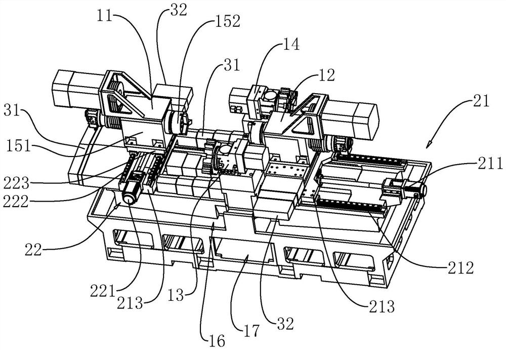
[0041] refer to figure 1 with figure 2 , the lateral movement mechanism includes a first drive member 211, a first slide rail 212 and a first slide table 213 slidingly connected with the first slide rail 212, the first drive member 211 is fixedly installed on the base 1, and the first drive member 211 It is a linear slide table. In this embodiment, a screw-type linear slide table is used. The first slide rail 212 is fixedly installed on the machine base 1. There are two first slide rails 212 located on both sides of the first driving member 211. , the first driving member 211 is used to drive the first slide table 213 to move back and forth laterally, the longitudinal movement mechanism is installed on the first slide table 213, the lateral movement mechanism also includes a first telescopic cover assembly 31, and the first telescopic cover assembly 31 is located at the first slide table 213. Two sides of a sliding platform 213 are used to cover the first driving member 211 ...

Embodiment 2

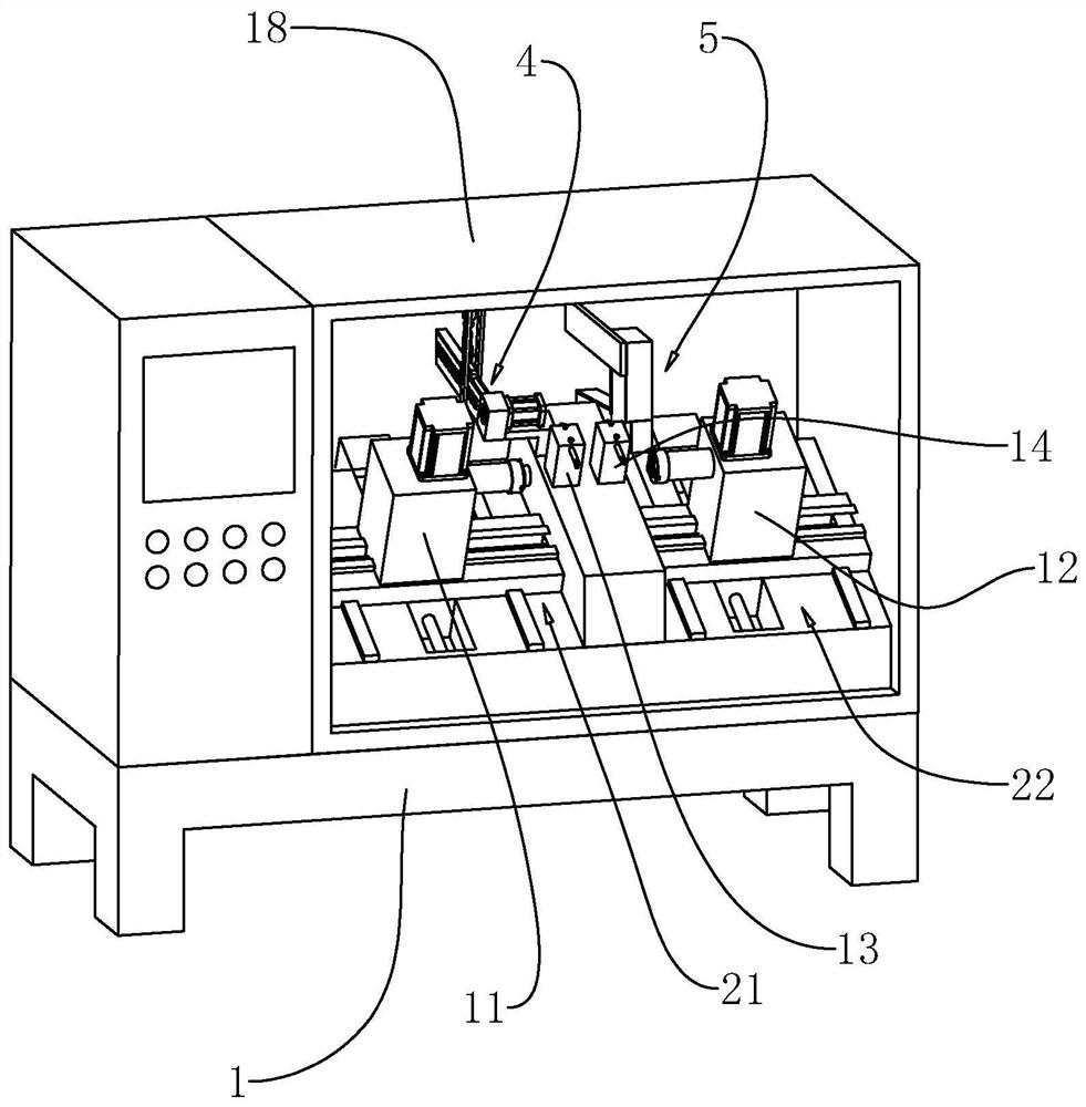
[0046] refer to image 3 with Figure 4 , in this embodiment, the workpiece is cylindrical or annular, and the first turret 13 and the second turret 14 are located on the same side of the machine base 1, and the machine base 1 is fixedly connected with a protective box 18, and on the machine base 1 Also be provided with feeding device 4, feeding device 4 comprises conveying mechanism and storage mechanism, and conveying mechanism comprises conveying material plate 41, is provided with the conveying groove 411 that is used to convey workpiece on the conveying material plate 41, and conveying material plate 41 is inclinedly arranged, The material storage mechanism includes a material storage block 45 on which a material storage tank 451 is arranged. The material storage block 45 is located below the conveying material plate 41 and the material storage tank 451 communicates with the conveying tank 411 . The conveying material plate 41 is inclined towards the material storage blo...


PUM


Abstract

The invention relates to a double-position machining numerical control machine tool and relates to the field of numerical control machine tools. The double-position machining numerical control machinetool comprises a machine base. A first clamping device and a second clamping device are symmetrically arranged on the machine base. The first clamping device and the second clamping device each comprise a three-jaw chuck and a fixed base, and the three-jaw chuck is mounted on the fixed base. A first tool turret and a second tool turret are arranged on the machine base. The first tool turret is paired with the first clamping device for use. The second tool turret is paired with the second clamping device for use. The machine base is further provided with a first moving device and a second moving device. The first moving device is used for driving the first clamping device to move. The second moving device is used for driving the second clamping device to move. The double-position machiningnumerical control machine tool has the effect of being easy to operate.

Description

technical field [0001] The present application relates to the field of numerical control machine tools, in particular to a double-station machining numerical control machine tool. Background technique [0002] CNC machine tool is the abbreviation of Computer numerical control machine tools, which is an automatic machine tool equipped with a program control system. [0003] When the existing CNC machine tools process the end face of the workpiece, the workpiece needs to be installed on the three-jaw chuck first, and the end face of the workpiece is processed through the tool holder, and then the workpiece is removed after the end face is processed. And reverse the direction, install it on the three-jaw chuck again, and process the other end face. [0004] With regard to the related technologies mentioned above, the inventor believes that there is a defect that the operation is relatively cumbersome. Contents of the invention [0005] In order to make the operation simpler...

Claims


Application Information

Patent Timeline
Patent Type & Authority Applications(China)
IPC IPC(8): B23B3/30B23B13/00B23B25/00B23Q7/04
CPCB23B3/30B23B13/00B23B25/00B23Q7/04
Inventor 宋春燕金翼
Owner 浙江震环数控机床股份有限公司
Why Eureka
Try Eureka