
Carton bending forming device and working method thereof

A bending forming and equipment technology, applied in papermaking, paper/cardboard container, box making operations, etc., can solve the problems of low feeding efficiency, inconvenient feeding work, increase processing cost, etc., so as to improve feeding efficiency and expand Scope of application, effect of reducing labor intensity

Inactive Publication Date: 2020-11-20
王娜娜
View PDF4 Cites 1 Cited by
  • Summary
  • Abstract
  • Description
  • Claims
  • Application Information

AI Technical Summary

Problems solved by technology

[0004] The purpose of the present invention is to provide a carton bending and forming equipment and its working method to solve the problem that most of the current carton bending and forming methods are manual bending or bending by simple pressing equipment, but most of these equipment require workers Manual feeding, the feeding efficiency is low, and the labor intensity of workers is increased; during the use of the existing carton bending and forming device, different types of equipment need to be used when bending cartons of different thicknesses and sizes, which improves the The cost of carton processing cannot be applied to the processing of cardboards of different sizes and thicknesses, and the application range of the device is small; during the use of the existing carton bending and forming device, when the processed carton is removed from the equipment, the card seat is on the long board It is easy to shake when moving, and it is easy to cause the second suction cup to absorb the carton and drop it, which is not convenient for unloading work, and the operation and use of the entire device cannot be completed by a single person

Method used


Image

  • Carton bending forming device and working method thereof
  • Carton bending forming device and working method thereof
  • Carton bending forming device and working method thereof

Examples


Embodiment Construction

[0030] The technical solutions of the present invention will be clearly and completely described below in conjunction with the embodiments. Apparently, the described embodiments are only some of the embodiments of the present invention, not all of them. Based on the embodiments of the present invention, all other embodiments obtained by persons of ordinary skill in the art without creative efforts fall within the protection scope of the present invention.

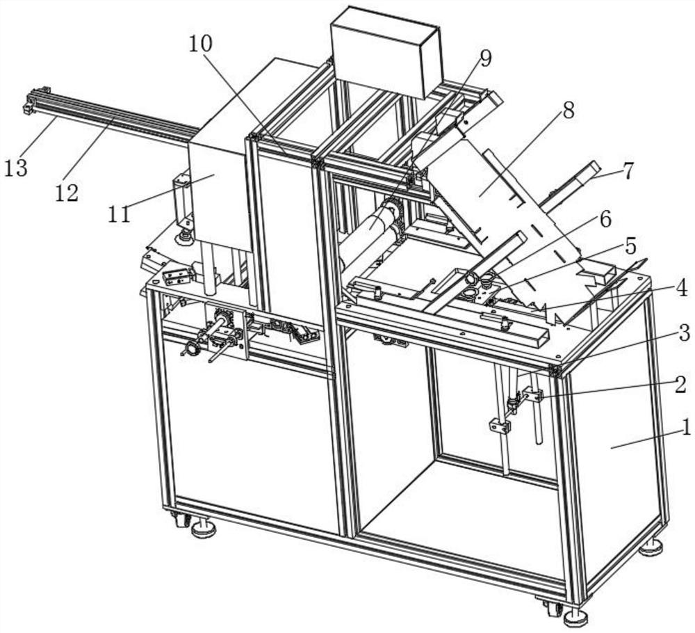
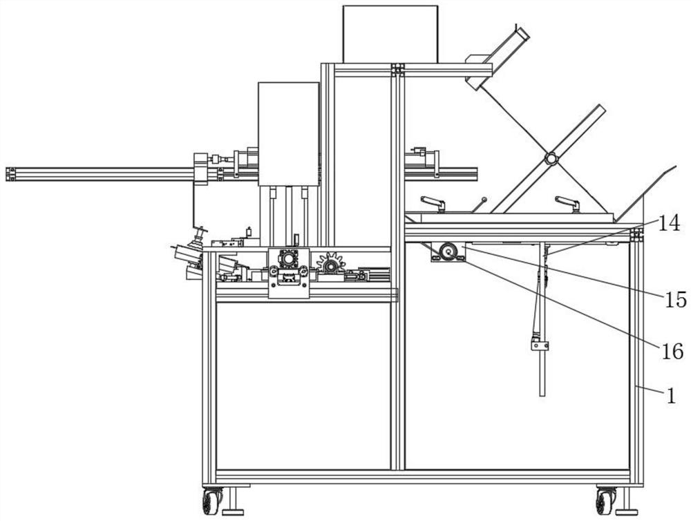
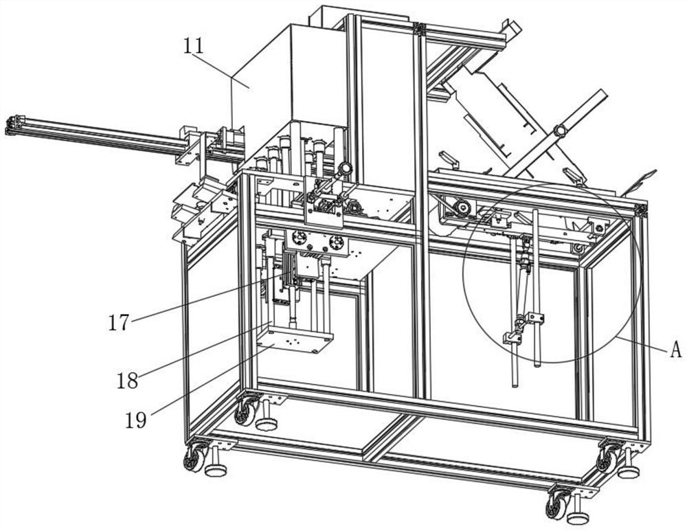
[0031] Such as Figure 1-6 As shown, a carton bending and forming equipment includes a bottom frame 1 and an intermediate frame 10, the top of the bottom frame 1 is provided with an intermediate frame 10, one side of the intermediate frame 10 is provided with a placement frame 7, and the cardboard 8 is placed on the Inside the frame 7, two vertical rods 14 are arranged below the placement frame 7, and the tops of the two vertical rods 14 are respectively arranged on the top inner wall of the bottom frame 1, and the two vert...


PUM


Abstract

The invention discloses a carton bending forming device. The device comprises a bottom frame and a middle frame, the middle frame is arranged at the top of the bottom frame, a placing frame is arranged on one side of the middle frame, a paperboard is placed in the placing frame, two vertical rods are arranged below the placing frame, the top ends of the two vertical rods are arranged on the innerwall of the top face of the bottom frame, fixing blocks are arranged on the two vertical rods correspondingly, and a first rotating rod is arranged between the two fixing blocks. According to the device, a paper box is sucked through a second suction cup, a third hydraulic cylinder controls a third piston rod therein to move towards the outer side of a cylinder body, a through hole is formed in asliding block, and a sliding rod penetrates through the interior of the through hole in the sliding block so that a clamping base can move along the sliding rod to move out the processed paper box from the device, the discharging work is facilitated, the situation that the paper box sucked by the second suction cup falls off due to shaking generated when the clamping base moves on a long plate isavoided, the discharging time is saved, the operation and use of the whole device can be completed by one person, and the manpower is saved.

Description

technical field [0001] The invention relates to the field of carton processing equipment, in particular to carton bending and forming equipment and a working method thereof. Background technique [0002] In the current era of online shopping, the use of cartons is increasing, especially for some fragile and fragile product items, which require the use of cardboard cartons. [0003] At present, most of the bending and forming methods of cartons are manual bending, or bending by simple pressing equipment, but most of these equipments require workers to manually load materials, and the feeding efficiency is low, which increases the labor intensity of workers; existing cartons During the use of the bending and forming device, different types of equipment are required to bend cartons of different thicknesses and sizes, which increases the cost of carton processing and cannot be applied to the processing of cardboards of different sizes and thicknesses. The scope of application of...

Claims


Application Information

Patent Timeline
IPC IPC(8): B31B50/52B31B50/44B31B50/04B31B50/00
CPCB31B50/006B31B50/04B31B50/44B31B50/52
Inventor 王璐
Owner 王娜娜
Learn More