
Buoy for marine environment monitoring and sampling

A marine environment monitoring and buoy technology, which is applied in the direction of buoys, sampling devices, floating buildings, etc., can solve problems such as prone to dumping, damage to floating tanks, and affecting monitoring results of monitoring devices, and achieve the effect of increasing service life and preventing erosion

Inactive Publication Date: 2020-11-20
苏州斯尔斯特新材料科技有限公司
View PDF0 Cites 9 Cited by
  • Summary
  • Abstract
  • Description
  • Claims
  • Application Information

AI Technical Summary

Problems solved by technology

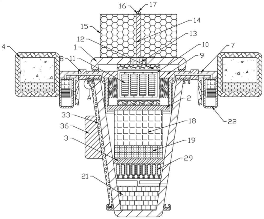
Most of the existing monitoring buoys have a simple structure and are prone to dumping when encountering wind and waves. Moreover, the buoys have been floating in the ocean for a long time, and impurities are easily attached to the outer surface of the floating box. The long-term erosion of impurities makes the floating box easy to damage and affects the monitoring results of the monitoring device.

Method used


Image

  • Buoy for marine environment monitoring and sampling
  • Buoy for marine environment monitoring and sampling
  • Buoy for marine environment monitoring and sampling

Examples


Embodiment 1

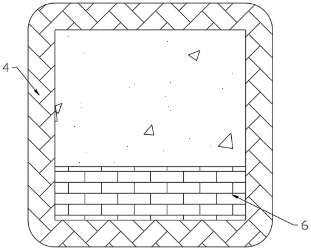
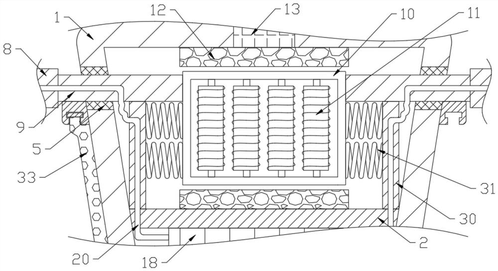
[0030] See Figure 1-7 , A buoy for marine environment monitoring and sampling, comprising a floating tank 1, a first partition 2 and a second partition 3 are arranged in the floating tank 1, a ring column 8 is provided on the outside of the floating tank 1, and the ring column 8 passes through a number of connecting rods 7 is connected to the floating component, the ring column 8 is connected to the power generating component on the upper side of the first partition 2 in the floating box 1 through the moving column 9, a signal transmitter 13 is provided in the wall of the floating box 1, and the upper side of the floating box 1 Solar power generation components are provided. A power module 18 and a master control terminal 19 are provided between the first partition 2 and the second partition 3. The lower ends of the connecting rods 7 are provided with mobile components. The power modules 18 are electrically connected to the mobile components through wires 20. In a sexual conne...

Embodiment 2

[0049] Further improvements are made on the basis of embodiment 1, and the improvements are as follows: a sealing block 5 is provided at the connection between the moving column 9 and the floating box 1, and the sealing block 5 is slidingly connected to the moving column 9, and the material of the sealing block 5 is selected as poly Tetrafluoroethylene prevents seawater from leaking into the floating box 2 at the sliding part of the movable column 9 and the floating box 1 through the setting of the sealing block 5.


PUM


Abstract

The invention discloses a buoy for marine environment monitoring and sampling. The buoy comprises a floating box, a first partition plate, a second partition plate, a signal transmitter, a power supply module, a master control terminal, a second balancing weight and a sampling assembly are arranged in the floating box; an annular column is arranged on the outer sides of the floating box; the annular column is connected with the floating assembly through a plurality of connecting rods; the annular column is connected with a power generation assembly for power generation on the upper side of thefirst partition plate in the floating box through a moving column, a solar power generation assembly is arranged on the upper side of the floating box, moving assemblies are arranged at the lower ends of the connecting rods, the power supply module is electrically connected with the moving assemblies through wires, and a scraping assembly for scraping off surface attachments is arranged at the side end of the floating box. Through the work of the floating box with the conical cross section, an air bag filled with the compressed air and a balance weight, the whole buoy stably floats on the seasurface, and the floating box is not prone to toppling over; reflected light of the reflector and power provided by the power supply module enable the warning lamp to work, all ships can be prompted,and the ships are prevented from colliding with the floating box.

Description

Technical field [0001] The invention relates to the field of marine environment monitoring, in particular to a buoy for marine environment monitoring and sampling. Background technique [0002] In recent years, with the continuous expansion of business areas, the monitoring center has developed monitoring and evaluation technology as the basis, with monitoring business as the core, and oriented to meet the national marine environmental management needs, forming a comprehensive marine ecology-sea area use-environmental monitoring The various monitoring products prepared by the monitoring center include national or regional marine economic development plans, marine functional zoning, the formulation of key marine environmental protection plans, the proposal of mitigation countermeasures for marine environmental disasters, and the decision-making of actions to respond to global climate change. It provides strong technical support. The monitoring buoy is a common platform for marine ...

Claims


Application Information

Patent Timeline
Patent Type & Authority Applications(China)
IPC IPC(8): B63B22/00B63B22/16B63B35/44G01N1/20
CPCB63B22/00B63B22/166B63B35/44B63B2035/4453G01N1/20
Inventor 胡培培
Owner 苏州斯尔斯特新材料科技有限公司
Learn More