
Air-based launched heavy reusable aerospace vehicle system

An aerospace vehicle, air launch technology, applied in launch systems, aerospace vehicles, aircraft and other directions, can solve problems such as poor structural strength design, poor mounting, and difficulty in mounting large-size and heavy-weight aerospace vehicles. , to achieve the effect of reducing volume and weight

Pending Publication Date: 2020-11-20
中国航空研究院
View PDF0 Cites 3 Cited by
  • Summary
  • Abstract
  • Description
  • Claims
  • Application Information

AI Technical Summary

Problems solved by technology

[0006] However, the mounting methods of the straight wing and the central wing bridge of these two systems are weak in structural design, and it is difficult to mount large-scale and heavy-weight aerospace vehicles, because the height and width are restricted by the height and width of the wing bridge, and the maximum speed is too low to cause rapid pressure. If it is too low, it will affect the load capacity of the aircraft, that is, the weight of aerospace vehicles. For example, although the "stratospheric launcher" carrier aircraft has a wingspan of 120 meters, its speed is low due to the use of straight wings, and the maximum total take-off weight is only 580 tons. , not as good as the An-225 aircraft of the former Soviet Union during the Cold War, with a maximum take-off gross weight of 640 tons, but a wingspan of only 88 meters, because of its higher cruising speed
[0007] To sum up, the current large-scale twin-fuselage layout aircraft has a central wing bridge mount launch mode, and its structural strength design is not as good as that of a large wing-body fusion body. The mount is not as limited as the back load, and the speed is low.
Although the use of metal hydrogen fuel can achieve the first-stage orbiting of the aircraft, it still takes a long time for the development of the theory of metal hydrogen production and industrialization.

Method used


Image

  • Air-based launched heavy reusable aerospace vehicle system
  • Air-based launched heavy reusable aerospace vehicle system

Examples


Embodiment Construction

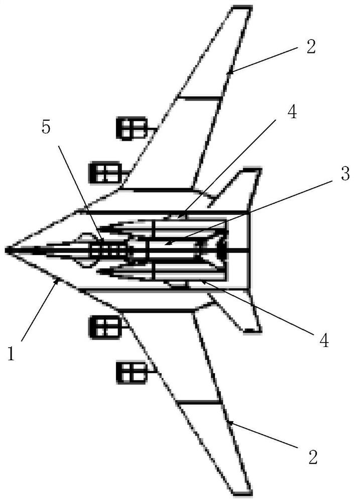
[0028] The heavy-duty reusable aerospace vehicle system for space-based launch of the present invention, compared with the space-based launch system mounted on the central wing bridge of a large-scale dual-fuselage layout aircraft, adopts a large-scale wing-body fusion layout transonic aircraft back-loaded aerospace vehicle in the air Launching, the wing-body fusion layout aircraft is used as a carrier aircraft, and it is used as a carrier aircraft. The allowable speed is large, the speed pressure is large, and the wing area is large, which is conducive to increasing the load capacity.

[0029] Among them, the carrier aircraft adopts the aerodynamic layout of wing-body fusion to make a smooth transition between fuselage 1 and wing 2, instead of the obvious distinction between wing 2 and fuselage 1 as in traditional passenger aircraft. The purpose of this is to reduce the exposed area of ​​the aircraft and make the The contact area between the aircraft and the air is as small as...


PUM


Abstract

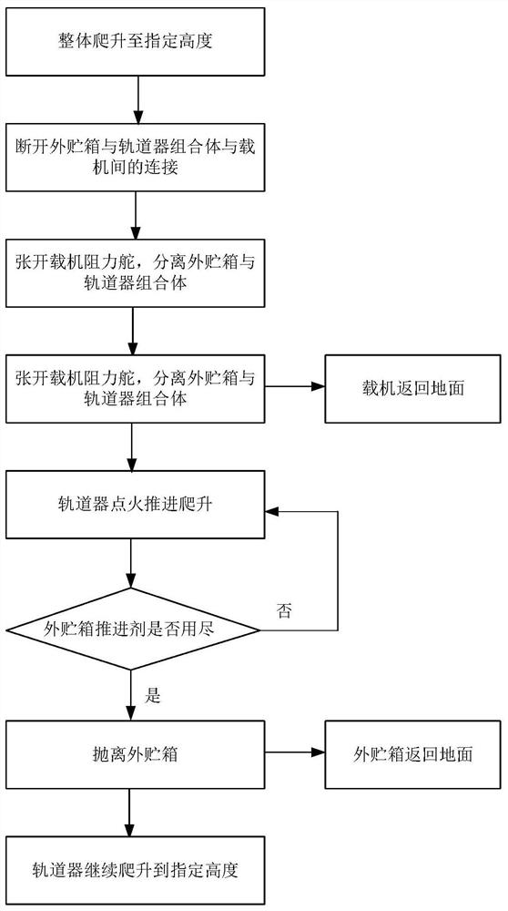
The invention discloses an air-based launched heavy reusable aerospace vehicle system. A transonic aircraft back-loaded aerospace vehicle is launched in the air by adopting a large-scale wing body fusion layout. The aerospace vehicle comprises an orbiter and two outer storage tanks. A carrier aircraft carries the orbiter, and the two outer storage tanks are symmetrically installed on the two sidesof the orbiter. When air-based launching is carried out, the aircraft firstly climbs to a specified height, and then a combined body of the outer storage tank and the orbiter is separated so that theorbiter climbs to the storage tank, a propellant is exhausted, and the outer storage tank is thrown away. And finally, the orbiter continuously accelerates and adjusts a posture to a specified heightto do circular motion around the earth. Cost of launching the heavy reusable aerospace vehicle is greatly reduced, and a proportion of injection weight to total take-off weight is greatly increased.

Description

technical field [0001] The invention relates to an aerospace vehicle system, in particular to an air-launched heavy-duty reusable aerospace vehicle system. Background technique [0002] 75% of the earth's atmospheric mass is concentrated in the troposphere. The dense atmosphere of the troposphere not only provides the resistance of the aircraft, but also seriously reduces the thrust of the rocket engine (thrust loss is about 10% to 15%. Generally, a land-based multi-stage rocket enters orbit. The weight is only on the order of 3% of the total take-off weight), if the aerospace vehicle can be launched at the bottom of the flat layer above the troposphere, the use of propellant can be greatly reduced, and the weight ratio of the orbit can be significantly improved. In addition, the aircraft can take off horizontally, The lift-climb mode does not require the use of an oxidant, which is a very effective way to save the total take-off weight, because aero-engines can absorb oxyge...

Claims


Application Information

Patent Timeline
IPC IPC(8): B64G1/00
CPCB64G1/005
Inventor 雷国东李岩徐悦
Owner 中国航空研究院
Learn More