
Conveying mechanism for can processing

A transmission mechanism and canning technology, which is applied in the direction of conveyors, conveyor objects, transportation and packaging, etc., can solve the problems of single function of the conveyor belt, unfavorable automatic production, high labor cost, etc., to facilitate screening and flow, and reduce labor intensity and labor costs, the effect of simple device structure

Inactive Publication Date: 2020-11-20
宿州皇冠食品有限公司
View PDF6 Cites 4 Cited by
  • Summary
  • Abstract
  • Description
  • Claims
  • Application Information

AI Technical Summary

Problems solved by technology

[0002] Cans often need to be conveyed through the conveyor belt during canning processing. The current conveyor belt has a single function, and it is difficult to adjust the opening direction of the cans to the same direction when conveying the cans. It is often necessary to manually sieve and adjust the cans during the conveying process, so that The opening direction of the cans is consistent, which is convenient for subsequent processing. However, manual adjustment is labor-intensive and labor-intensive, and it is not conducive to automatic production. Therefore, we propose a can processing transmission mechanism to solve the above problems.

Method used


Image

  • Conveying mechanism for can processing
  • Conveying mechanism for can processing
  • Conveying mechanism for can processing

Examples


Embodiment Construction

[0019] The following will clearly and completely describe the technical solutions in the embodiments of the present invention with reference to the accompanying drawings in the embodiments of the present invention. Obviously, the described embodiments are only some, not all, embodiments of the present invention. Based on the embodiments of the present invention, all other embodiments obtained by persons of ordinary skill in the art without making creative efforts belong to the protection scope of the present invention.

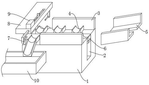
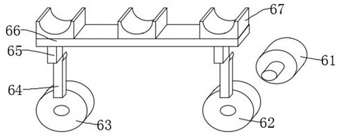
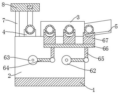
[0020] see Figure 1-4 , the present invention provides a technical solution: a can processing transmission mechanism, including a base 1, a mounting groove 2 is opened in the middle of the top surface of the base 1, and a plurality of positioning seats 4 are fixedly installed on the top of the base 1 on both sides of the mounting groove 2, The guide plate 3 is fixedly installed on the base 1 on the side of the positioning seat 4 away from the installation gro...


PUM


Abstract

The invention discloses a conveying mechanism for can processing. The conveying mechanism comprises a base, wherein a mounting groove is formed in the middle of the base, multiple positioning seats are mounted in the positions, located at the top of the base, of two sides of the mounting groove, guide plates are mounted on the base, chutes are mounted in the positions, located on the side walls ofthe base, of two sides of the mounting groove, each chute is connected with one end of the corresponding guide plate, a positioning mechanism is mounted between inner walls of the mounting groove, astand column is fixedly mounted at the top of the end, away from the chutes, of the base, a top plate is fixedly mounted at the top of the stand column, a shunting mechanism is mounted on the top plate and directly faces the positioning seats away from the chutes, and conveying belts are mounted on the outer wall of the end, away from the chutes, of the base. According to the conveying mechanism for can processing, canned bottles are conveyed to the chutes through the conveying belts in a unified manner and slide to the side walls of the base along the chutes, the canned bottles are placed onthe positioning seats one by one by the positioning mechanism, positioning for the canned bottles is realized, the canned bottles on the positioning seats away from the chutes are pushed to the conveying belts on the two sides of the base by the shunting mechanism, so that the opening direction of the canned bottles on each conveying belt are consistent, the canned bottles are automatically adjusted and conveyed, and subsequent processing and production are facilitated.

Description

technical field [0001] The invention relates to the technical field of can processing, in particular to a can processing transmission mechanism. Background technique [0002] Cans often need to be conveyed through the conveyor belt during canning processing. The current conveyor belt has a single function, and it is difficult to adjust the opening direction of the cans to the same direction when conveying the cans. It is often necessary to manually sieve and adjust the cans during the conveying process, so that The opening direction of the cans is consistent, which is convenient for subsequent processing. However, manual adjustment is labor-intensive and labor-intensive, and it is not conducive to automatic production. Therefore, we propose a can processing transmission mechanism to solve the above problems. Contents of the invention [0003] The purpose of the present invention is to provide a can processing conveying mechanism to solve the problems raised in the above-me...

Claims


Application Information

Patent Timeline
IPC IPC(8): B65G47/04B65G47/26B65G25/04B65G47/82B65G47/46B65G47/44
CPCB65G25/04B65G47/04B65G47/26B65G47/44B65G47/46B65G47/82
Inventor 崔虔
Owner 宿州皇冠食品有限公司
Learn More