


Quick Research
Generate reliable direction feasibility study reports for your R&D in just a few steps.

Technical Q&A
Discover and master advanced knowledge NOW. Basics, ideas, possibilities, all at once.

Find Solutions
As an expert in R&D theories, this can generate solutions to your technical problems instantly.

Evaluate Feasibility
Analyze your overall solution with one click, know your potential R&D risks in advance.

Monitor Landscape
Get weekly tech updates, stay abreast of the latest tech innovations and key insights.
Support for built-in composite thermal insulating wall system and joint structure
A composite thermal insulation and system technology, applied in thermal insulation, building structure, building components, etc., can solve problems such as unfavorable building energy conservation, and achieve the effect of improving thermal insulation performance
- Summary
- Abstract
- Description
- Claims
- Application Information
AI Technical Summary
Problems solved by technology
Method used
Image

Examples
Embodiment 1
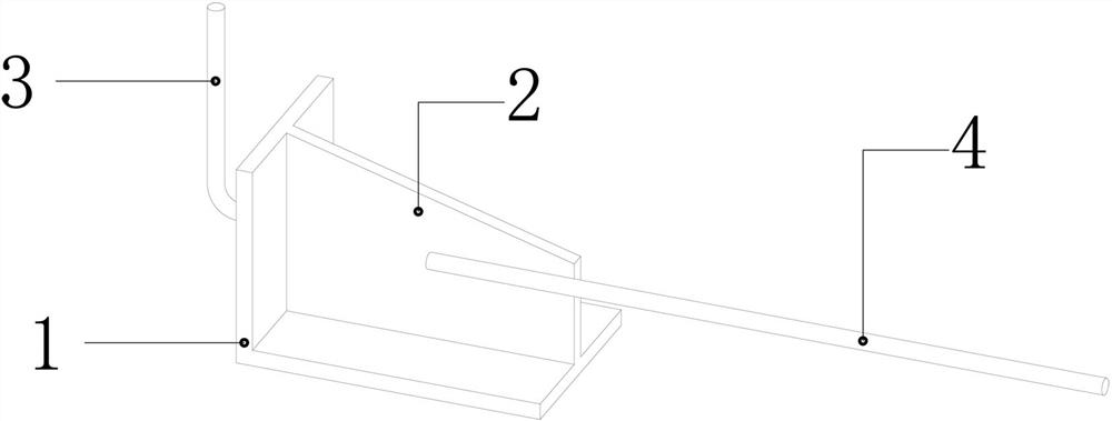
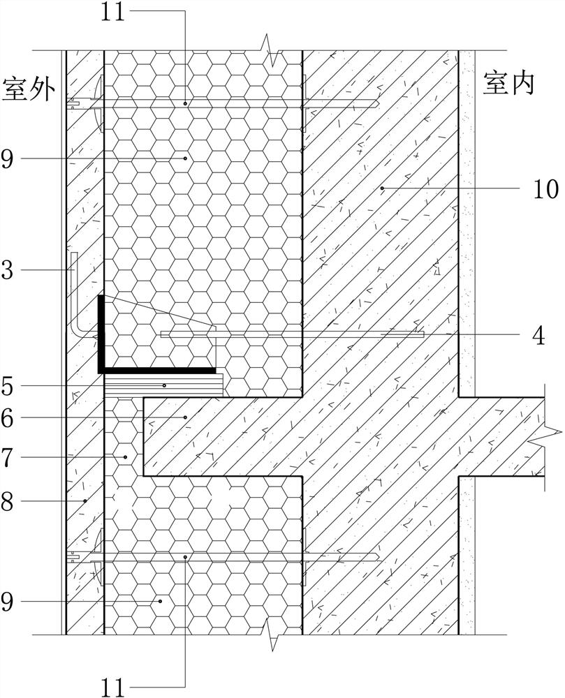
[0026] as attached figure 2 As shown, the node structure of this embodiment includes a fireproof structure layer 8 , an insulation layer 9 and a base wall 10 arranged in sequence from the outdoor to the indoor direction, and a pick plate 6 is provided outside the base wall 10 . The vertical side wall of the right-angle plate 1 of the support is located between the fireproof structure layer 8 and the insulation layer 9, and its bottom plate corresponds to the pick-up plate 6, and a heat-insulating pad 5 is provided between the bottom plate of the right-angle plate 1 and the pick-up plate 6 , between the outer wall of the pick plate 6 and the fireproof construction layer 8, there is an anti-cold bridge insulation layer 7, the first anchor piece 3 of the supporting plate is installed in the fireproof construction layer 8 in an L shape, and the second anchor piece 4 passes through After the thermal insulation layer 9 enters in the base wall body 10 .
[0027] The heat insulation...
Embodiment 2
[0031] as attached image 3 As shown, this embodiment is improved on the basis of Embodiment 1, the structure of the pick plate 6 is canceled, the pick plate 6 is replaced by the lower support 12, and the rest of the structure remains unchanged.
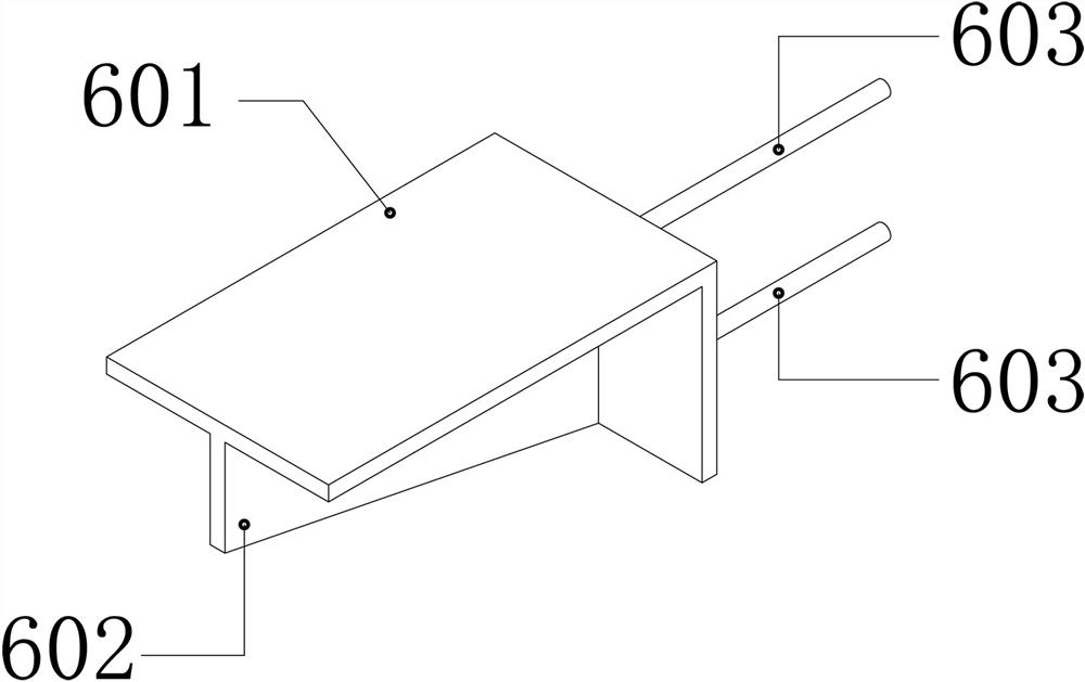
[0032] as attached Figure 4 As shown, the lower support 12 includes a lower right-angle plate 601, a lower stiffener 602 arranged on the inner side of the right angle of the lower right-angle plate 601, and a lower anchor 603 arranged on the side wall of the lower right-angle plate 601, and the heat insulation pad 5 is arranged on the lower right-angle plate 601 above the top surface. Two lower anchors 603 are arranged in parallel, the side wall of the lower right-angle plate 601 is located between the insulation layer 9 and the base wall 10 , and the lower anchor 603 is arranged in the base wall 10 . Generally speaking, the structure of the lower support 12 is similar to that of the support, except that the design of the second a...
PUM
| Property | Measurement | Unit |
|---|---|---|
| Compressive strength | aaaaa | aaaaa |
Abstract
Description
Claims
Application Information
 - R&D Engineer
- R&D Manager
- IP Professional
- Industry Leading Data Capabilities
- Powerful AI technology
- Patent DNA Extraction
Browse by: Latest US Patents, China's latest patents, Technical Efficacy Thesaurus, Application Domain, Technology Topic, Popular Technical Reports.
© 2024 PatSnap. All rights reserved.Legal|Privacy policy|Modern Slavery Act Transparency Statement|Sitemap|About US| Contact US: help@patsnap.com