Separate splicing form board straight splicing joint plugging device and method

A technology for blocking device and splicing seam, which is applied to the connection of formwork/template/work frame, the preparation of building components on site, construction, etc., which can solve the difficulty of excavation and leveling of raised structures and the inability to seal the splicing seam. , decoration and other troublesome problems, to achieve the effect of improving construction quality and demolition speed, reducing construction cost and convenient operation

Pending Publication Date: 2020-11-20
陕西有色建设有限公司
View PDF0 Cites 5 Cited by
  • Summary
  • Abstract
  • Description
  • Claims
  • Application Information

AI Technical Summary

Problems solved by technology

[0002] With the further optimization of engineering and building construction, the previous floor splicing is gradually transformed into concrete pouring, and for large-area pouring surfaces, for road surfaces, in order to meet the needs of expansion joints, generally block pouring is required; for floors and other infiltration Floor slab structures with strict requirements generally require overall pouring, and for large-area pouring, a large-area pouring surface is generally formed by splicing multiple splicing formwork. During the installation process, although loose formwork (wooden formwork, plastic formwork) has certain advantages in economy, there are common quality problems of grout leakage due to lax joints between formworks, and the joints between formworks cannot be sealed. The risk of slurry leakage, and at the same time, a raised structure caused by material leakage is formed between the splicing joints. It is difficult to excavate and level the raised structure in the later stage, which will cause great trouble to the later decoration treatment

Method used


Image

  • Separate splicing form board straight splicing joint plugging device and method
  • Separate splicing form board straight splicing joint plugging device and method
  • Separate splicing form board straight splicing joint plugging device and method

Examples


Embodiment Construction

[0028] The present invention is described in further detail below in conjunction with accompanying drawing:

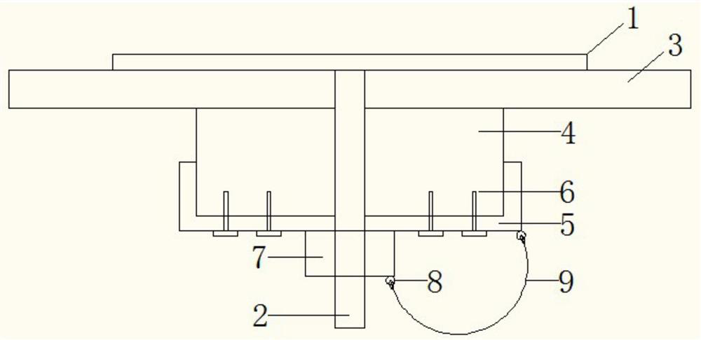
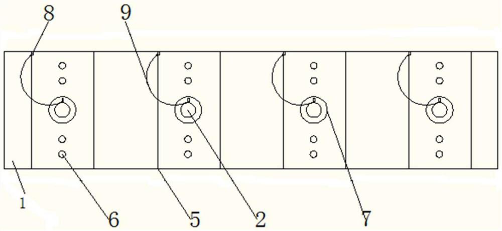
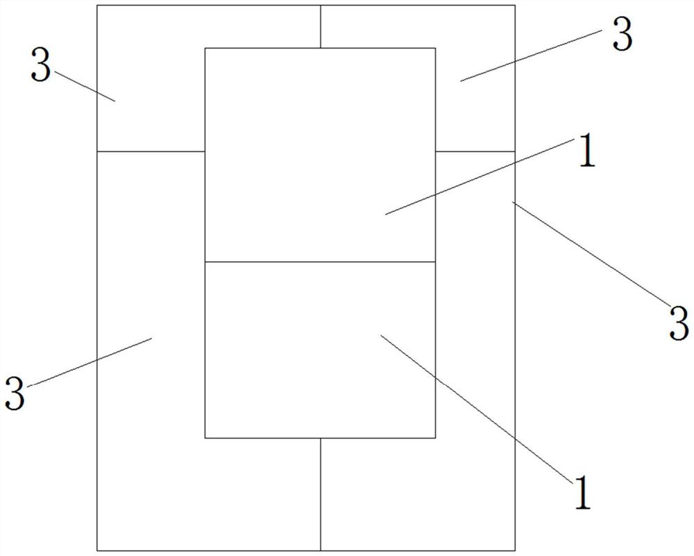
[0029] Such as figure 1 As shown, a flat splicing seam sealing device for loose formwork, including a base plate 1, a pressing block 4 and a pressing buckle plate 5, the base plate 1 is provided with a screw rod 2 perpendicular to the base plate 1, when splicing and pressing, The screw rod 2 on the bottom plate 1 is located between the gap between the two splicing templates 3, the width of the bottom plate 1 is not greater than the joint width of the two splicing templates 3, the splicing template 3 is located between the bottom plate 1 and the pressing block 4, the bottom plate 1 and the pressing block The tight block 4 is locked by the lock nut 7, and the compression buckle 5 is arranged between the lock nut 7 and the compression block 4, so as to ensure that the lock nut 7 can compact the compression blocks 4 on both sides. When splicing is required, the two splici...


PUM


Abstract

The invention discloses a separate splicing form board straight splicing joint plugging device and method. The method comprises the steps that a base plate provided with a lead screw and a tightly-pressing buckle plate are adopted for separate splicing form board straight splicing joint plugging operation; after splicing form boards and tightly-pressing blocks are mounted based on the base plate,firstly, the lead screw is sleeved with the tightly-pressing buckle plate, so that the tightly-pressing blocks are clamped and pressed, and pin bolts are driven into the tightly-pressing blocks; and then, on the basis of the principle that a nut is screwed onto the lead screw, the tightly-pressing blocks are fastened, and the splicing form boards are compacted. The base plate is located at a straight splicing joint, and it is guaranteed that no slurry leaks due to the height difference between the surfaces of the adjacent splicing form boards; by means of splicing joints formed between the adjacent splicing form boards and between the tightly-pressing blocks, on one hand, the splicing joints can cooperate with the nut to achieve the effects that the tightly-pressing blocks are supported firmly and the splicing form boards are compacted conveniently, and on the other hand, the effect that when the form boards are dismounted, the form boards are dismounted wholly and rapidly by virtue ofthe external force for drawing the lead screw can be achieved conveniently; and the tightly-pressing buckle plate is located between the tightly-pressing blocks and the nut when the two adjacent splicing form boards are spliced, on one hand, the effect that the tightly-pressing buckle plate is clamped and buckled is achieved, and on the other hand, the effect that the tightly-pressing buckle plate cooperates with the nut to replace a fastening gasket is achieved; and the separate splicing form board straight splicing joint plugging device is simple in structure and convenient to operate.

Description

technical field [0001] The invention belongs to the technical field of loose formwork construction, and in particular relates to a sealing device and method for flat splicing joints of a loose formwork. Background technique [0002] With the further optimization of engineering and building construction, the previous floor splicing is gradually transformed into concrete pouring, and for large-area pouring surfaces, for road surfaces, in order to meet the needs of expansion joints, generally block pouring is required; for floors and other infiltration Floor slab structures with strict requirements generally require overall pouring, and for large-area pouring, a large-area pouring surface is generally formed by splicing multiple splicing formwork. During the installation process, although loose formwork (wooden formwork, plastic formwork) has certain advantages in economy, there are common quality problems of grout leakage due to lax joints between formworks, and the joints bet...

Claims


Application Information

Patent Timeline
Patent Type & Authority Applications(China)
IPC IPC(8): E04G17/00
CPCE04G17/00E04G17/005
Inventor 肖莹莹吕红辉董岳涛刘伟朋柏小伟高梦茹杨策何佩谦
Owner 陕西有色建设有限公司
Why Eureka
Try Eureka