Dual seal combined type valve
A double-seal and combined technology, applied in shaft seals, valve details, control valves, etc., can solve the problems of complex structure and poor sealing of combined valves, and achieve stable and reliable movement, simple structure, and easy maintenance and replacement Effect
- Summary
- Abstract
- Description
- Claims
- Application Information
AI Technical Summary
Problems solved by technology
Method used
Image

Examples
Embodiment 1
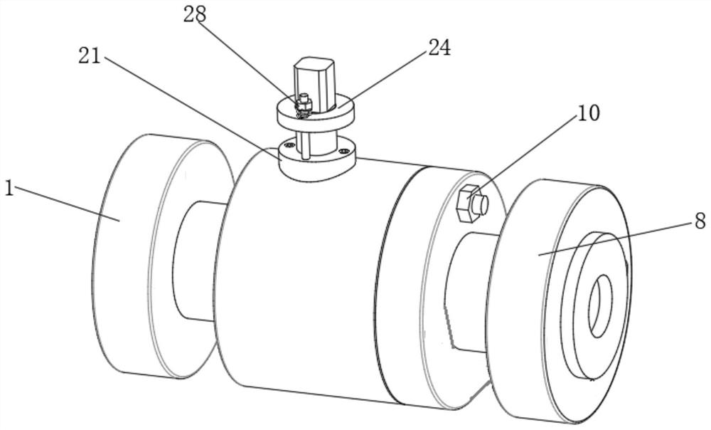
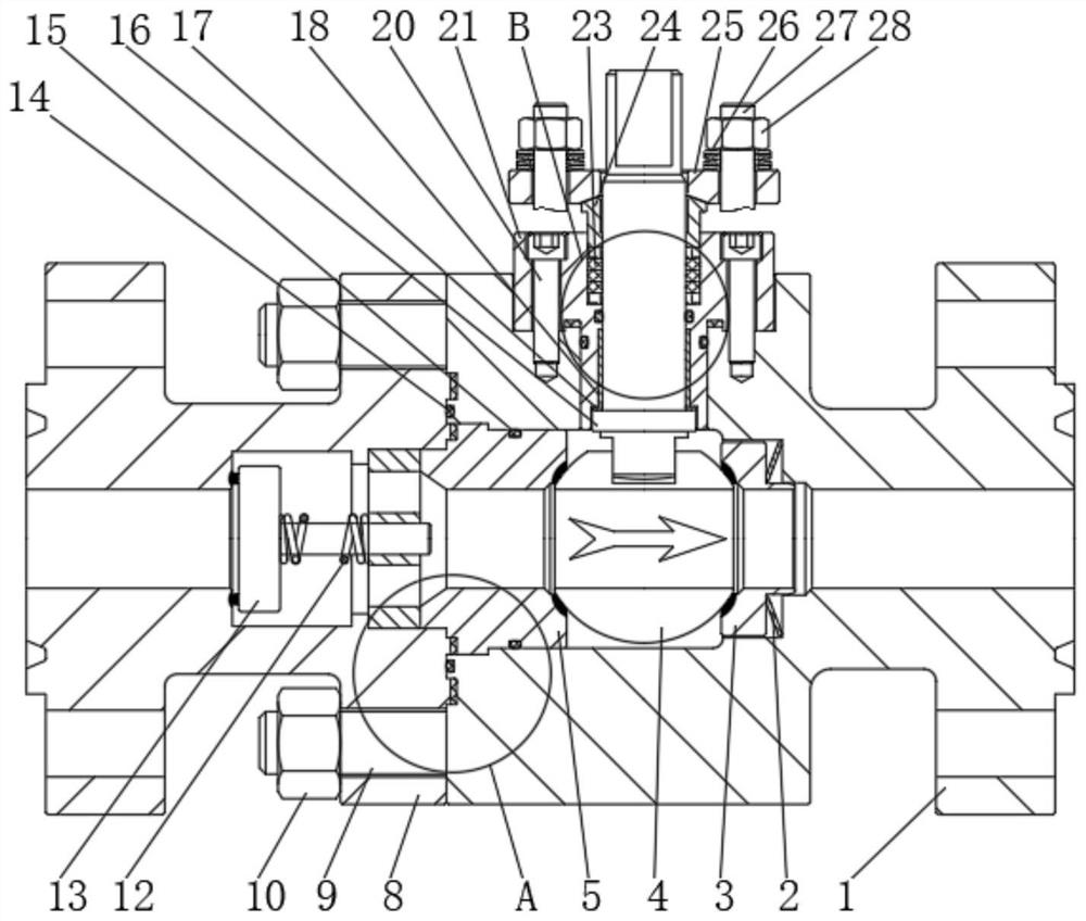
[0029] Please refer to Figure 1-2, a double-seal combined valve, including a first valve body 1, a first disc spring 2 is fixedly connected to the inner side of the first valve body 1, and one side of the first disc spring 2 A first valve seat 3 is provided, a valve ball 4 is provided on one side of the first valve seat 3, a valve stem 16 is provided on the top of the valve ball 4, a stuffing box 21 is provided on the top of the first valve body 1, and a stuffing box 21 is provided on the top of the valve ball 4. There are first packing 22 and second packing 23 inside, the top of the stuffing box 21 is fixedly connected with the packing gland 24, the top of the packing gland 24 is fixedly connected with the packing plate 25, and the two sides of the packing plate 25 are penetrated with the second Stud 27, the top outside of the second stud 27 is threadedly connected with the second nut 28, the outer side of the second stud 27 is sleeved with the second disc spring 26, and the s...
Embodiment 2
[0032] Referring to Fig. 2-3, this embodiment is further optimized on the basis of embodiment 1, specifically, the outer side of the second valve seat 5 is sleeved with a second O-ring 15, the stuffing box 21 and the first A third sealing ring 19 is provided between the valve bodies 1 .
[0033] Specifically, a third O-ring 29 is provided outside the middle of the valve stem 16 .
[0034] Specifically, a fourth O-ring 30 is sleeved on the outside of the bottom of the stuffing box 21 .
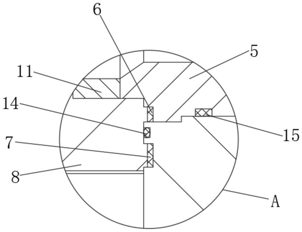
[0035] Specifically, a first seal ring 6, a second seal ring 7 and a first O-ring 14 are provided between the first valve body 1 and the second valve body 8, and an axial flow seal is provided inside one end of the first butterfly spring 2. One end of the axial flow valve disc 13 is sleeved with a coil spring 12 , and one end of the first butterfly spring 2 is fixedly connected with a support seat 11 .
[0036] In this embodiment, through the cooperation between the second O-ring 15, the thir...
Embodiment 3
[0038] Please refer to Fig. 2 and 4, present embodiment has been optimized as follows on the basis of example 1 or example 2, specifically, between the first valve body 1 and the second valve body 8 through the first stud 9 and the first Nut 10 is fixedly connected.
[0039] Specifically, a plane bearing 17 is sleeved on the outside of the bottom of the valve stem 16 , and a sliding bearing 18 is provided on the top of the plane bearing 17 , and the sliding bearing 18 is sleeved on the outside of the valve stem 16 .
[0040] Specifically, the stuffing box 21 is provided with screws 20 inside.
[0041] In this embodiment, when the valve stem 16 is in motion, due to the effect of the plane bearing 17 and the sliding bearing 18, the frictional force on the valve stem 16 during the motion is reduced, thereby preventing the valve stem 16 from being strained, effectively The service life of the device is extended.
[0042] To sum up: the present invention uses the second butterfly...
PUM
 Abstract
Description
Claims
Application Information
 - R&D Engineer
- R&D Manager
- IP Professional
- Industry Leading Data Capabilities
- Powerful AI technology
- Patent DNA Extraction
Browse by: Latest US Patents, China's latest patents, Technical Efficacy Thesaurus, Application Domain, Technology Topic.
© 2024 PatSnap. All rights reserved.Legal|Privacy policy|Modern Slavery Act Transparency Statement|Sitemap