
Vehicle-mounted umbrella storage device

A technology for umbrella storage and water removal, which is applied in the direction of rack configuration, drying solid materials, chemical instruments and methods, etc., can solve the problems of unable to remove water from long-stem umbrellas, unable to clean and wash umbrellas, etc., and achieves simple structure and improved practicality sexual effect

Active Publication Date: 2020-11-20
JIANGSU XINGCHENXING AUTO ACCESSORIES
View PDF18 Cites 2 Cited by
  • Summary
  • Abstract
  • Description
  • Claims
  • Application Information

AI Technical Summary

Problems solved by technology

[0005]Aiming at the deficiencies in the prior art, the present invention provides a vehicle-mounted umbrella storage device, which has a simple structure and works through one power source, not only realizing long In addition to the dehydration effect of the long-stem umbrella, it also realizes the effect of washing and cleaning the outer wall of the long-stem umbrella multiple times. The present invention filters the water body thrown out of the umbrella, and then flushes the outer wall of the long-stem umbrella again, thereby achieving the effect of coordinating the washing, and Fully benefiting the thrown rainwater and utilizing it, the invention not only realizes the washing and cleaning of the long-stem umbrella, but also achieves the advantages of dehydration and dehydration, and solves the problem that the prior art can only carry out simple rainwater collection on the long-stem umbrella , it is impossible to perform good dewatering and dehydration effects on long-stem umbrellas. Secondly, when the existing technology collects rainwater on long-stem umbrellas, it is impossible to clean and scrub the umbrellas.

Method used


Image

  • Vehicle-mounted umbrella storage device
  • Vehicle-mounted umbrella storage device
  • Vehicle-mounted umbrella storage device

Examples


Embodiment Construction

[0034]The following will clearly and completely describe the technical solutions in the embodiments of the present invention with reference to the accompanying drawings in the embodiments of the present invention. Obviously, the described embodiments are only some, not all, embodiments of the present invention. Based on the embodiments of the present invention, all other embodiments obtained by persons of ordinary skill in the art without making creative efforts belong to the protection scope of the present invention.

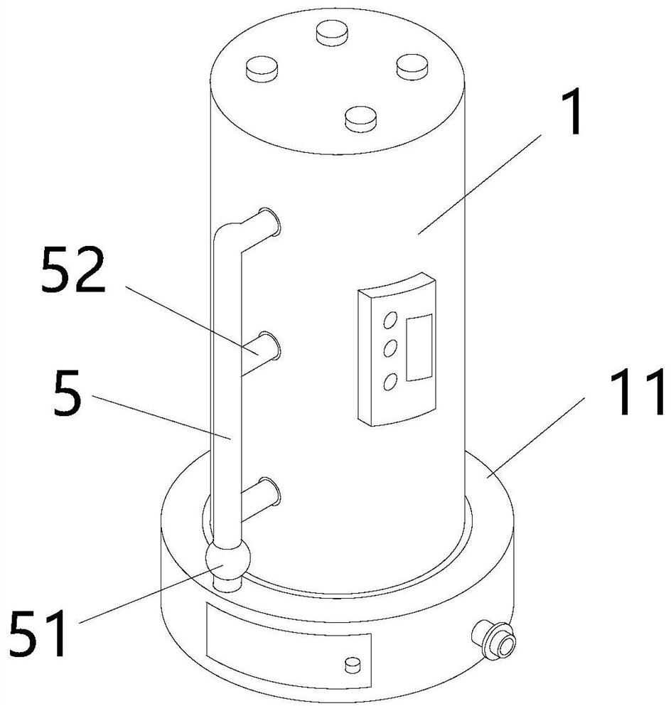
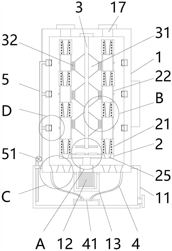
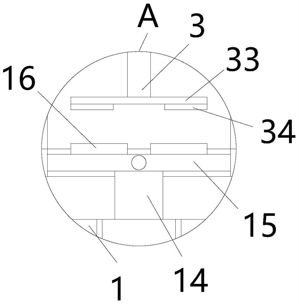
[0035] see Figure 1-11 , the present invention provides a technical solution: a vehicle-mounted umbrella storage device, including a water spinner 1, a water tank 11 and a servo motor 12, the servo motor 12 is fixedly installed at the bottom of the water spinner 1, and the water tank 11 is fixedly installed at the bottom of the water spinner 1 On the outer wall, a cover body 13 is fixedly installed at the bottom of the water throwing cylinder 1 and the servo m...


PUM


Abstract

The invention relates to the technical field of vehicle-mounted equipment, and discloses a vehicle-mounted umbrella storage device. The vehicle-mounted umbrella storage device comprises a water-spinning barrel, a water tank and a servo motor, wherein a rotating column is fixedly arranged at the output end of the servo motor; a cross-shaped rotating rod is fixedly arranged on the top of the rotating column; rotating rings are fixedly arranged on the outer wall of the rotating rod; and combinations of rotating rings and limiting sleeves being assembled one above the other at intervals are arranged on the tops of the rotating rings. The vehicle-mounted umbrella storage device is simple in structure. Through work of a power source, not only the dehydration effect of a long-rod umbrella is achieved, but also the repeated washing-cleaning effect is achieved for the outer wall of the long-rod umbrella, a water body spun from an umbrella is filtered, and then the outer wall of the long-rod umbrella is washed, so that the effect of washing in a matching way is achieved. Moreover, the spun rain water is utilized fully and reused, the long-rod umbrella can be dehydrated easily and rapidly after passengers get on vehicles, the rainwater on the long-rod umbrella is prevented from falling in a bus, and the problem of wet and slip ground in the vehicles is solved.

Description

technical field [0001] The invention relates to the technical field of vehicle equipment, in particular to a vehicle umbrella storage device. Background technique [0002] On rainy days, when passengers carrying long umbrellas take a bus, before entering the bus, they need to shake the umbrella on the outer wall of the long umbrella once, in order to dry the water on the outer wall of the umbrella as much as possible, but through artificial The drying of the long-stem umbrella does not guarantee that the outer wall of the long-stem umbrella will not be stained with water. It will still cause rainwater to follow the umbrella and fall into the bus, causing the problem of slippery bus ground. [0003] The general design of the umbrella storage device on the bus of the prior art is relatively simple. It can only collect simple rainwater for the long-stem umbrella, and cannot perform good water rejection and dehydration effects on the long-stem umbrella. Secondly, the existing te...

Claims


Application Information

Patent Timeline
Patent Type & Authority Applications(China)
IPC IPC(8): F26B5/08F26B25/00B60R7/12B08B1/04
CPCF26B5/08F26B25/00B60R7/12B08B1/32Y02A20/108
Inventor 王德有
Owner JIANGSU XINGCHENXING AUTO ACCESSORIES
Learn More