Supercharge Your Innovation With Domain-Expert AI Agents!

Battery system sensor fault diagnosis method based on state estimation method

A technology for sensor faults and battery systems, applied in instruments, measuring electronics, electric vehicles, etc., can solve problems such as increased power and SOC changes, increased false alarm rates in fault diagnosis, etc., to achieve small calculations and reduce false alarm rates and the effect of the false alarm rate

Active Publication Date: 2020-11-20
HARBIN INST OF TECH AT WEIHAI +1
View PDF12 Cites 1 Cited by
  • Summary
  • Abstract
  • Description
  • Claims
  • Application Information

AI Technical Summary

Problems solved by technology

In the current research, the starting point data is fixed and the end point data is continuously updated with the increase of sampling time, which will lead to the gradual increase of the power and SOC changes in the later stage of discharge, which will lead to an increase in the failure rate of fault diagnosis.

Method used


Image

  • Battery system sensor fault diagnosis method based on state estimation method
  • Battery system sensor fault diagnosis method based on state estimation method
  • Battery system sensor fault diagnosis method based on state estimation method

Examples


Embodiment Construction

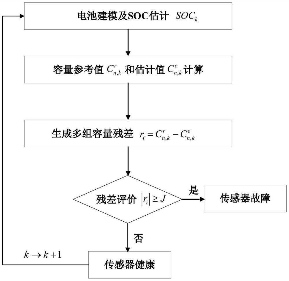
[0028] Below is a 3.6V LiFePO 4 The battery provides a detailed description of the sensor fault diagnosis method provided by the present invention in conjunction with the accompanying drawings. A battery system sensor fault diagnosis method based on the state estimation method provided by the present invention, such as figure 1 As shown, it specifically includes the following steps:

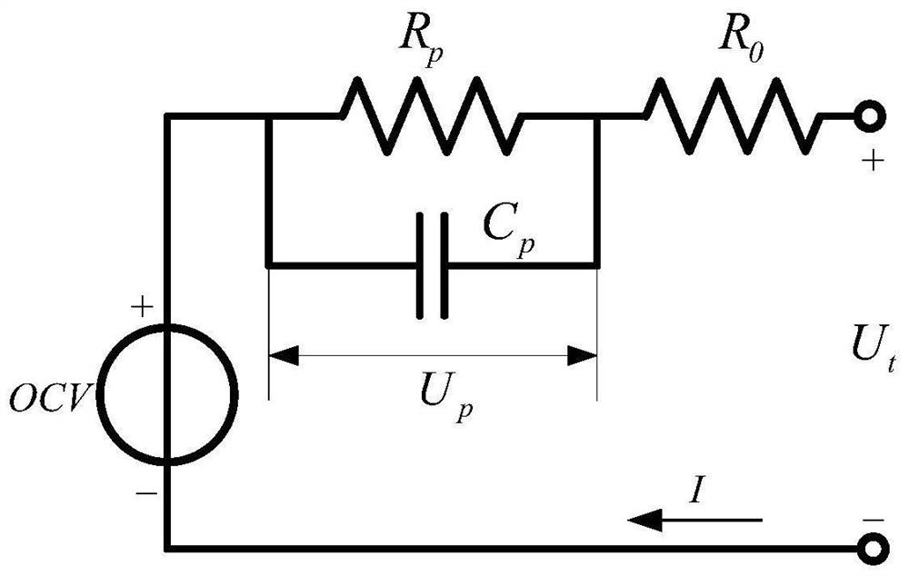
[0029] Step 1: Build as figure 2 The Thevenin equivalent circuit model is shown, which consists of three parts: voltage source, ohmic internal resistance, and RC network. The discrete mathematical expression for this model is:

[0030]

[0031] In the formula, k is the sampling time, U t is the terminal voltage, U p is the polarization voltage, OCV is the open circuit voltage of the battery, and its value can be expressed as a sixth-order polynomial of SOC: OCV=f(SOC), the polynomial coefficient is determined by OCV experiment; I is the battery current, R 0 is the ohmic internal resista...


PUM


Abstract

The invention provides a battery system sensor fault diagnosis method based on a state estimation method. The method comprises the following steps : pr constructing a battery model is constructed, then, carrying out real-time estimation on the state of charge of the battery by adopting a model-based method; determining the capacity of the battery by adopting a ratio of the electric quantity changeto the state of charge change within a certain time period; respectively acquiring a capacity reference value and five groups of capacity estimation values by changing initial moments correspondingto a starting point and an ending point of a used time period; and respectively carrying out difference treatment on the capacity reference value and the estimated value to obtain five groups of capacity residual errors, respectively comparing the five groups of capacity residual errors with a threshold value, and judging that the sensor has a fault when the absolute value of one or more groups ofresidual errors reaches or exceeds the threshold value.

Description

technical field [0001] The invention relates to the field of power battery systems, in particular to a battery system sensor fault diagnosis method based on a state estimation method. Background technique [0002] Sensor fault diagnosis is one of the core functions of the battery management system (BMS), which is of great significance to the safety of the battery system. BMS performs modeling and battery state estimation based on the data collected by sensors, so using battery state changes for sensor fault diagnosis is one of the typical approaches. The state of the battery includes state of charge (State of charge, SOC), state of energy (state of energy, SOE) and state of health (state of health, SOH), and SOH is mainly measured by capacity decline. Therefore, the SOC, SOE and capacity C of the battery can be used n The corresponding residuals are generated for sensor fault diagnosis. In fact, the change rates of the three are different during the charge and discharge c...

Claims


Application Information

Patent Timeline
IPC IPC(8): G01R31/367G01R31/378G01R31/382
CPCG01R31/367G01R31/378G01R31/382Y02T10/70
Inventor 于全庆万长江金毅王大方杨博文郝志伟张毕董浩崧李宪营俄立新
Owner HARBIN INST OF TECH AT WEIHAI
Features
  • R&D
  • Intellectual Property
  • Life Sciences
  • Materials
  • Tech Scout
  • Unparalleled Data Quality
  • Higher Quality Content
  • 60% Fewer Hallucinations
Learn More