
Radio frequency multi-chirp linear frequency modulation stepping signal generation method and device

A technology of linear frequency modulation stepping and signal generation, which is applied in the direction of radio wave measurement systems and instruments, can solve the problems of inability to measure distance, high cost of equipment, difficulty in obtaining coherent light sources, etc., and achieve chirp stepping parameters and bandwidth. control effect

Pending Publication Date: 2020-11-20
NANJING UNIV OF AERONAUTICS & ASTRONAUTICS
View PDF2 Cites 8 Cited by
  • Summary
  • Abstract
  • Description
  • Claims
  • Application Information

AI Technical Summary

Problems solved by technology

Su Yuanyuan et al. in "Optical LFM stepping signal synthesis and high-resolution ranging demonstration" (Su Yuanyuan, Wu Jin, Zhao Zhilong, et al. Optical LFM stepping signal synthesis and high-resolution ranging demonstration[J]. Intense Lasers and Particle Beams, 2014,26(10):101016.) In this article, discrete lasers are used to synthesize a large-bandwidth chirp step signal (FSCS) laser signal source to achieve high-resolution ranging. The chirp step produced by this scheme Although the input signal bandwidth can be synthesized to achieve a large bandwidth, the chirp rate is single and range measurement cannot be performed, which has certain application limitations. In this paper, multiple linear frequency modulation laser sources are required to synthesize the linear frequency modulation step signal, and the equipment cost Large, it is not easy to obtain a coherent light source by using multiple independent lasers at the same time, and the requirements for lasers are high

Method used


Image

  • Radio frequency multi-chirp linear frequency modulation stepping signal generation method and device
  • Radio frequency multi-chirp linear frequency modulation stepping signal generation method and device
  • Radio frequency multi-chirp linear frequency modulation stepping signal generation method and device

Examples


Embodiment Construction

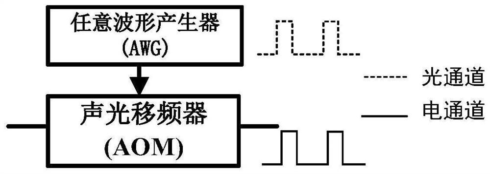
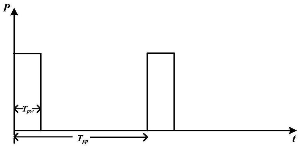
[0032]Aiming at the deficiencies of the existing technology, the solution idea of ​​the present invention is based on microwave photon technology, based on cyclic frequency shift loop to achieve larger bandwidth, and the generation of radio frequency multi-chirp linear frequency modulation step signal with controllable chirp step rate and bandwidth Program. Specifically, the single-frequency continuous optical carrier is converted into a periodic optical pulse signal by using an optical switch and then input into the cyclic frequency shifting loop; the chirp electrical pulse signal is input into the cyclic frequency shifting loop and is set to suppress the single sideband of the carrier The modulation mode of the electro-optic modulator, and the following conditions are satisfied: where T pw and T pp Respectively, the pulse width and period of the periodic light pulse signal, T OFSL For the delay introduced by the optical signal circulating once in the cyclic frequency shi...


PUM


Abstract

The invention discloses a radio frequency multi-chirp linear frequency modulation stepping signal generation method, which comprises the steps: converting a single-frequency continuous optical carrierinto a periodic optical pulse signal by utilizing an optical switch and then inputting the periodic optical pulse signal into a cyclic frequency shift loop; inputting the linear frequency modulationelectric pulse signal into an electro-optical modulator which is arranged in the cyclic frequency shift loop and is set to be in a mode of suppressing carrier single-sideband modulation, and letting the following conditions shown in the specification be met, wherein Tpw and Tpp are the pulse width and the period of the periodic optical pulse signal respectively, TOFSL is the time delay introducedwhen the optical signal is circulated once in the loop, and N is an integer greater than 1 and represents the number of times of circulation of the optical signal in the loop in one pulse period; andcombining the loop output signal with the beam splitting optical signal of the single-frequency continuous optical carrier, and then performing coherent detection to obtain a radio frequency multi-chirp linear frequency modulation stepping signal of which the chirp rate and the bandwidth are periodically increased. The invention further discloses a radio frequency multi-chirp linear frequency modulation stepping signal generation device. The chirp stepping parameters and bandwidth are controllable, and the signal bandwidth range is large.

Description

technical field [0001] The invention relates to a method for generating a radio frequency signal, in particular to a method for generating a radio frequency multi-chirp linear frequency modulation step signal. Background technique [0002] In the early radar system, the transmission signal used a single carrier frequency signal. The single frequency signal caused the two important indicators of the radar, the distance resolution and the velocity resolution, to restrict each other. The pulse compression technology solved this contradiction perfectly. In the pulse compression radar system, the commonly used signals are linear frequency modulation signal, nonlinear frequency modulation signal and phase encoding signal. Among them, the linear frequency modulation signal has become the most mature signal in the pulse compression radar because of its superior performance that is easy to generate and easy to process. [0003] The chirp signal has a large time-bandwidth product (Ti...

Claims


Application Information

Patent Timeline
Patent Type & Authority Applications(China)
IPC IPC(8): G01S7/484
CPCG01S7/484
Inventor 张亚梅潘时龙李露刘策马丛
Owner NANJING UNIV OF AERONAUTICS & ASTRONAUTICS
Learn More