An air pressure fixed cable tray used in a building

A cable tray and fixed technology, applied in electrical components and other directions, can solve problems such as troublesome operation of the limit structure, reduced heat dissipation effect, poor heat dissipation effect, etc., so as to avoid cable damage, ensure heat dissipation efficiency, and avoid internal air pressure leakage. Effect

Active Publication Date: 2021-09-28
天津龙鼎熙石化新能源科技有限公司
View PDF0 Cites 0 Cited by
  • Summary
  • Abstract
  • Description
  • Claims
  • Application Information

AI Technical Summary

Problems solved by technology

[0004] The object of the present invention is to provide a kind of air pressure fixed cable tray used in the building, to solve the above-mentioned background technology, there are generally many cables in the bridge tray, and the power of some cables is relatively large, and the current and voltage delivered are also relatively high. It will generate a large amount of heat on the surface. The existing heat dissipation structure is mostly a simple hole structure on the side wall, which cannot avoid dust invasion. At the same time, due to the distance from the cable, the heat dissipation effect is poor, and the existing In the technology, a correspondingly complex limiting structure will be used to limit the cable, resulting in further reduction of its heat dissipation effect, and the problem that the limiting structure is very troublesome to operate

Method used


Image

  • An air pressure fixed cable tray used in a building
  • An air pressure fixed cable tray used in a building
  • An air pressure fixed cable tray used in a building

Examples


Embodiment Construction

[0024] The following will clearly and completely describe the technical solutions in the embodiments of the present invention with reference to the accompanying drawings in the embodiments of the present invention. Obviously, the described embodiments are only some, not all, embodiments of the present invention. Based on the embodiments of the present invention, all other embodiments obtained by persons of ordinary skill in the art without making creative efforts belong to the protection scope of the present invention.

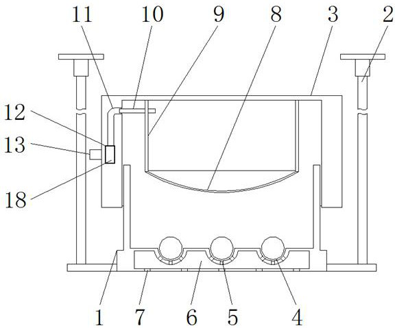
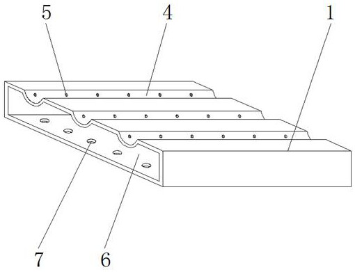
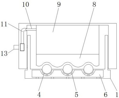
[0025] see Figure 1-7 , the present invention provides a technical solution: an air pressure fixed cable tray used in a building, including a trunking 1, a fixing rod 2, a cover plate 3, a receiving groove 4, a first air hole 5, a heat dissipation cavity 6, and a second air hole 7. Limiting sheet 8, air box 9, air pipe 10, first cavity 11, second cavity 12, first booster tube 13, sleeve 14, first baffle 15, second baffle 16, first Two booster tubes 17, self-...


PUM


Abstract

The invention discloses an air pressure fixed cable bridge used in a building, which comprises a wire groove, a fixing rod and a cover plate, the two sides of the wire groove are connected with the vertically distributed fixing rods, and a limited and the edge of the spacer is sealed and fixed at the bottom opening of the air box, and the spacer is made of elastic material, the top of the air box is fixed on the lower surface of the cover, and the sides of the air box and The trachea is connected, and the left end of the trachea is connected with the first cavity, and the first cavity is opened in the side wall of the cover plate. The air pressure fixed cable tray used in this building can limit and compress the cables inside the wire slot by means of air pressure adjustment. At the same time, the structural design of multiple air holes and cooling chambers can ensure the heat dissipation of high-power cables during operation. Efficiency, and the same inflation operation can be used to realize the convenient fixing of the cover plate and the trunking, and the fixing structure is hidden to avoid damage by others.

Description

technical field [0001] The invention relates to the technical field of cable installation, in particular to an air pressure fixed cable bridge used in buildings. Background technique [0002] Cable is an important basic profile in modern society, which plays the role of power and signal transmission. During its use, it needs to ensure the stability of its overall state. Therefore, it needs to use the corresponding installation structure. According to the different usage scenarios, the installation The structure is also different. The more common one is the bridge structure used in the interior of the building. Most of the existing bridges are composed of wire slots and cover plates. The following problems exist: [0003] There are generally many cables in the bridge, and some cables have high power and high current and voltage, so they will generate a lot of heat on the surface. Most of the existing heat dissipation structures are simple holes on the side wall. structure, ...

Claims


Application Information

Patent Timeline
Patent Type & Authority Patents(China)
IPC IPC(8): H02G3/04H02G3/03
CPCH02G3/03H02G3/0406H02G3/0456H02G3/0487
Inventor 韩世强
Owner 天津龙鼎熙石化新能源科技有限公司
Why Eureka
Try Eureka