A parallel loop heat pipe heat dissipation device used for heat dissipation of a server chip

A technology of chip heat dissipation and loop heat pipe, which is applied in the direction of instruments, circuits, and electrical solid devices, can solve the problems of huge auxiliary supporting systems, limited heat dissipation efficiency, and cumbersome maintenance in the later stage, so as to improve safety and reliability, and improve heat dissipation The effect of temperature control level and overall thermal resistance reduction

Pending Publication Date: 2019-01-18
CHINA ACAD OF AEROSPACE AERODYNAMICS
View PDF7 Cites 8 Cited by
  • Summary
  • Abstract
  • Description
  • Claims
  • Application Information

AI Technical Summary

Problems solved by technology

The single-phase liquid cooling circuit is to directly transport the liquid to the surface of the heating chip through the pipeline to take away the heat, and the immersion liquid cooling is to immerse the chip directly in the liquid. However, both of these two methods have huge auxiliary systems, high costs, and The post-maintenance is cumbersome, there are problems such as leakage safety hazards, and limited by the structure and internal space of the server, the heat dissipation efficiency is limited

Method used


Image

  • A parallel loop heat pipe heat dissipation device used for heat dissipation of a server chip
  • A parallel loop heat pipe heat dissipation device used for heat dissipation of a server chip
  • A parallel loop heat pipe heat dissipation device used for heat dissipation of a server chip

Examples


Embodiment 1

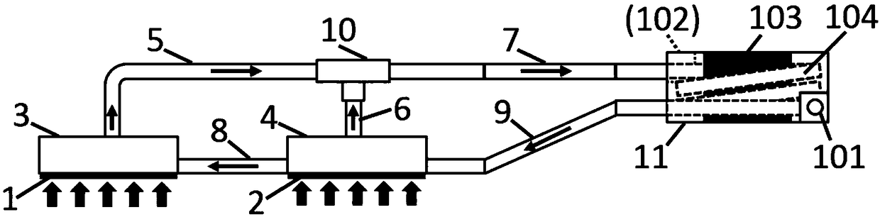
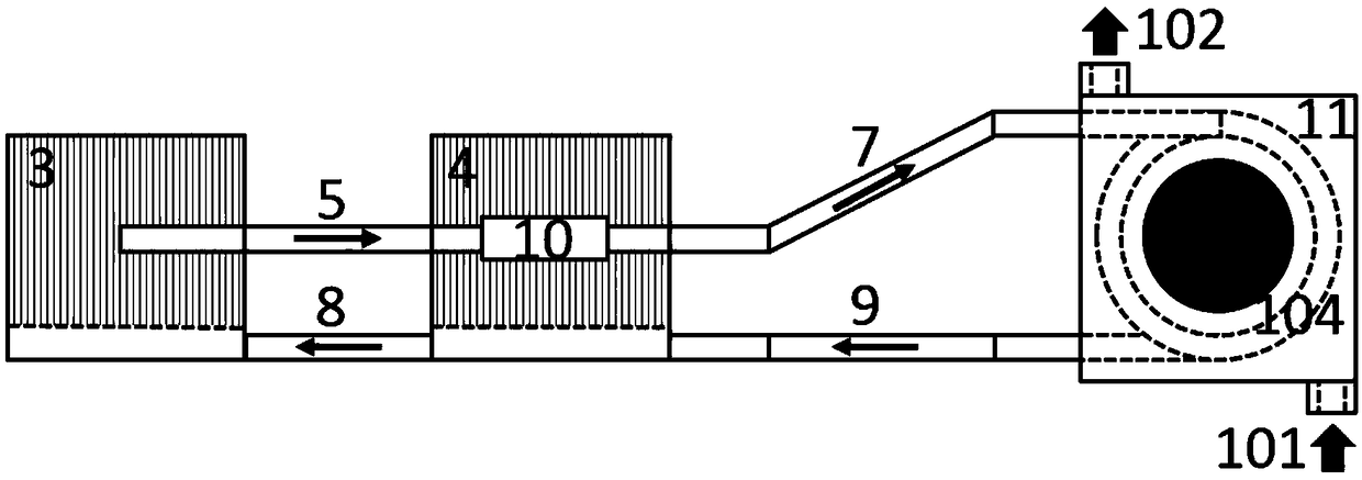
[0029] Referring to FIG. 1( a ) and FIG. 1( b ), there is shown a schematic structural diagram of a parallel loop heat pipe cooling device for cooling server chips in an embodiment of the present invention. In this embodiment, the parallel loop heat pipe cooling device used for server chip heat dissipation, the parallel loop heat pipe includes: a second evaporator 3, a first evaporator 4, a second gas pipeline 5, a first An evaporation pipeline 6 , a first gas pipeline 7 , a second liquid pipeline 8 , a first liquid pipeline 9 , a tee structure 10 , and a cooling box 11 .

[0030]The first liquid pipeline 9 is connected to the first evaporator 4, the first evaporator 4 is connected to the second evaporator 3 through the second liquid pipeline 8, and the second evaporator 3 is connected to the tee structure through the second gas pipeline 5 10. At the same time, the three-way structure 10 is connected to the first evaporator 4 through the first evaporation pipeline 6, and conne...

Embodiment 2

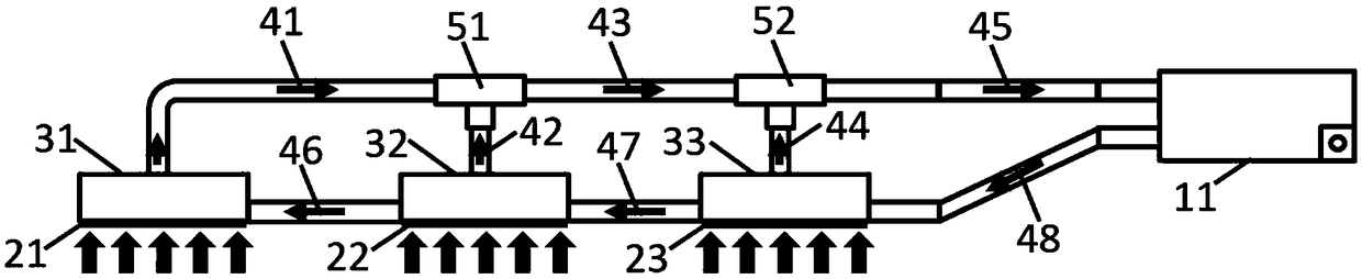
[0036] The present invention is not limited to the situation that two chips dissipate heat at the same time, and can be extended to three chips and is not limited to the situation that the CPU chip dissipates heat at the same time. Referring to FIG. 2( a ) and FIG. 2( b ), there is shown a schematic structural view of a three-evaporator parallel loop heat pipe cooling device for heat dissipation of server chips in an embodiment of the present invention.

[0037] In this embodiment, the parallel loop heat pipe cooling device used for server chip heat dissipation, the parallel loop heat pipe includes: a first evaporator 33, a second evaporator 32, a third evaporator 31, a first liquid Pipeline 48, second liquid pipeline 47, third liquid pipeline 46, third gas pipeline 41, second gas pipeline 43, first gas pipeline 45, second steam pipeline 42, first steam pipeline road 44 , the second three-way structure 51 , the first three-way structure 52 and the cooling box 11 .

[0038] Th...


PUM


Abstract

The invention discloses a parallel loop heat pipe heat dissipation device used for heat dissipation of a server chip, which comprises a cooling box, N evaporators, N-1 three-way structure, N-section gas lines, N-section liquid line sand N-1 evaporation lines; N evaporators pass through the evaporation pipeline, a liquid line and a gas line are connecte in parallel to that cooling box; At that sametime, the first gas line extend into the cooling box, A loop of coil is formed inside that cooling box, A coil extends out of the cooling box and communicates with the liquid line of the first section, the N evaporator extends into the interior of the server and contact N chips and fixed with the N chips; The heat generated in the working process on the chip evaporates the liquid in the evaporator into gas, which is sent to the cooling box by the evaporation pipeline and the gas pipeline, and the cooling fluid in the cooling box is heat exchanged with the cooling fluid in the cooling box andcondensed into liquid, thereby realizing the chip heat dissipation, N >= 1. The invention simplifies the heat dissipation structure, improves the heat dissipation efficiency, and reduces the energy consumption cost and the potential safety hazard.

Description

technical field [0001] The invention belongs to the technical field of heat dissipation in computer rooms, and relates to a parallel loop heat pipe heat dissipation device used for heat dissipation of server chips. Background technique [0002] With the increase of data center scale and cabinet power density, the heat dissipation and energy consumption of data centers (also known as computer rooms) has attracted more and more attention and attention. The traditional heat dissipation methods of data centers are mainly air-conditioning air cooling systems and single-phase circulating water cooling systems. Among them, the air-conditioning air-cooling system has a simple structure and is the easiest to implement, but has limited heat dissipation capacity and high energy consumption; the water-cooling system has a strong heat dissipation capacity, but the system is large and complex, and the water-cooling pipeline is generally arranged outside the machine room or cabinet for saf...

Claims


Application Information

Patent Timeline
Patent Type & Authority Applications(China)
IPC IPC(8): H01L23/427H01L23/473G06F1/20
CPCG06F1/20H01L23/427H01L23/473G06F2200/201Y02D10/00
Inventor 谢铭慧薛志虎陈思员俞继军艾邦成李炜曲伟
Owner CHINA ACAD OF AEROSPACE AERODYNAMICS
Why Eureka
Try Eureka