Integrated CT induction electricity taking circuit and device

An inductive power-taking, integrated technology, applied in circuit devices, emergency protection circuit devices, emergency protection circuit devices for limiting overcurrent/overvoltage, etc. loss, high efficiency, and ensure stable results

Pending Publication Date: 2020-11-20
深圳市嘉创达电源科技有限公司
View PDF0 Cites 0 Cited by
  • Summary
  • Abstract
  • Description
  • Claims
  • Application Information

AI Technical Summary

Problems solved by technology

[0004] The integrated CT induction power-taking circuit and device provided by the present invention, the power-taking circuit can realize the discharge absorption under the overcurrent state, protect the following circuit from being damaged, and eliminate the impact on the CT when the current of the high-voltage transmission line fluctuates in a large range. The interference of the output of the power-taking device ensures the normal operation of the load. The power-taking device can solve the huge fluctuation of the cable current caused by the high-voltage cable during the low and peak periods of power consumption. The ordinary power-taking device cannot solve the problem of extremely low current and high current. When problems occur on the same cable at the same time, it has the advantages of small size, light weight, high power, extremely low heat generation, high efficiency, low cost, convenient installation, and more stable performance.

Method used


Image

  • Integrated CT induction electricity taking circuit and device
  • Integrated CT induction electricity taking circuit and device
  • Integrated CT induction electricity taking circuit and device

Examples


Embodiment 1

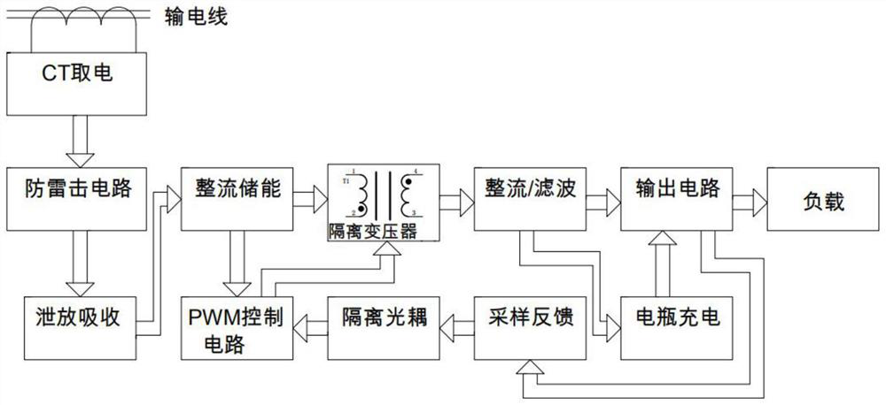
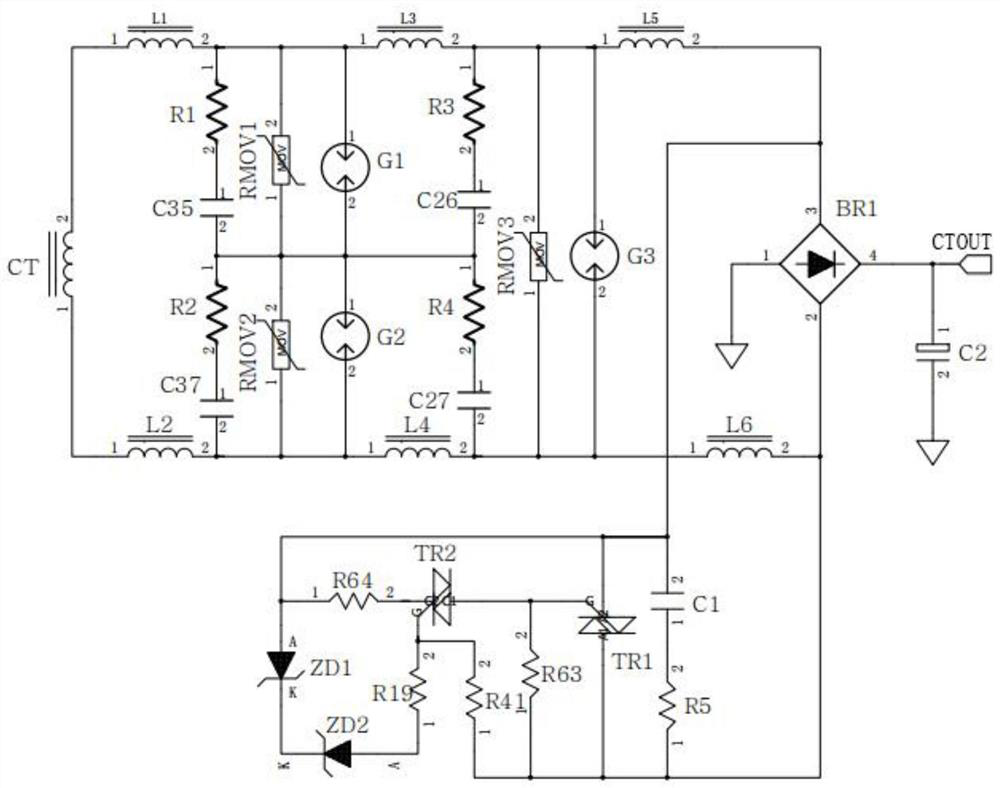
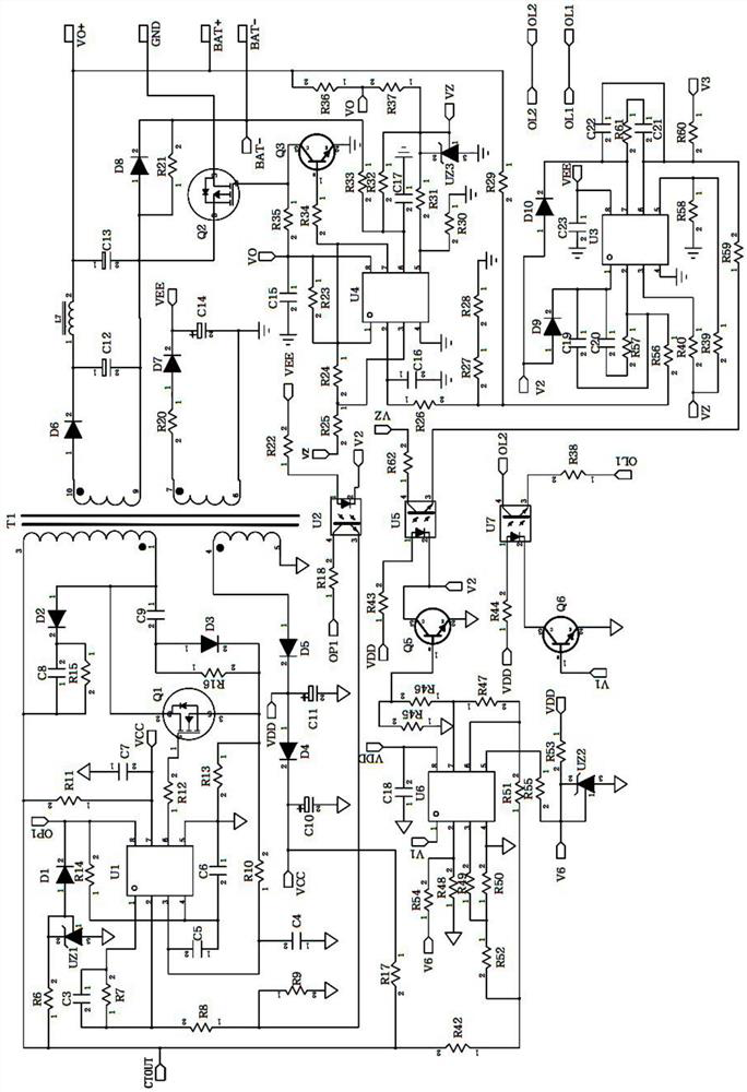
[0027] like figure 1 , figure 2 as well as image 3 As shown, the integrated CT induction power-taking circuit in this embodiment includes a CT induction input circuit, a lightning protection circuit, a discharge absorption circuit, and a rectification energy storage circuit. The input terminal of the lightning protection circuit and the secondary side of the CT induction input circuit The output terminal is connected. The output terminal of the lightning protection circuit is connected to the discharge absorption circuit. The discharge absorption circuit is used to conduct when the output voltage of the lightning protection circuit exceeds the threshold. The primary side of the CT sensor is installed in the power grid, and the secondary side The CT sensing input circuit is connected to the lightning protection circuit. In this embodiment, the lightning protection circuit includes a primary protection circuit and a secondary protection circuit. The two output terminals on t...

Embodiment 2

[0036] The difference between this embodiment and Embodiment 1 is that the integrated CT induction power-taking device in this embodiment has multiple sets of CT induction power-taking circuits, and when one power-taking circuit cannot meet the demand, multiple power-taking circuits can be set according to the demand. The configuration of the electric circuit is more flexible. In this embodiment, there are two groups of CT induction electric circuits.


PUM


Abstract

The invention relates to the technical field of high-voltage line power taking, especially to an integrated CT induction electricity taking circuit and device. The integrated CT induction electricitytaking circuit comprises a CT induction input circuit, a lightning protection circuit and a discharge absorption circuit. The output end of the secondary side of the CT induction input circuit is connected with the lightning protection circuit, the output end of the lightning protection circuit is connected with a discharge absorption circuit, and the discharge absorption circuit is used for beingswitched on when the output voltage of the lightning protection circuit exceeds a threshold value. The integrated CT induction electricity taking device comprises the CT induction electricity takingcircuit and an output circuit. According to the integrated CT induction electricity taking circuit and device, interference on output of the CT electricity taking device when current of a high-voltagetransmission line fluctuates in a large range can be eliminated, normal work of a load is guaranteed, the problem that a common electricity taking device cannot solve the problem that extremely low current and extremely high current occur on the same cable at the same time is solved, and the CT electricity taking device has the advantages of small size, light weight, high power, high efficiency,convenience in installation, more stable performance and the like.

Description

technical field [0001] The invention relates to the technical field of high-voltage line power extraction, in particular to an integrated CT induction power extraction circuit and device. Background technique [0002] At present, the power supply methods of high-voltage smart appliances are: direct power supply of transformer, power supply of electromagnetic voltage transformer (PT) or power supply of capacitive voltage transformer (CTV), power supply of CT, power supply of solar power generation, power supply of laser, power supply of capacitor series voltage divider Power supply, capacitive current limiting step-down power supply, but these have many disadvantages. [0003] The main function of high-voltage transformers and electromagnetic voltage transformers or capacitive voltage transformers is to realize voltage conversion, which is not only large in size and high in cost, but the scope of use is limited, especially not suitable for primary conversion power supplies or...

Claims


Application Information

Patent Timeline
Patent Type & Authority Applications(China)
IPC IPC(8): H02H9/04H02H9/06H02J9/06
CPCH02H9/041H02H9/06H02J9/061Y02B70/30Y04S20/20
Inventor 刘将
Owner 深圳市嘉创达电源科技有限公司
Why Eureka
Try Eureka