Power rotary purification device for smoke collecting demister and purification method

A purification device, fog machine technology, applied in chemical instruments and methods, separation methods, gas treatment and other directions, can solve the problems of poor purification effect, backward technology, large volume, etc., achieve good absorption and purification effect, remove harmful components and odor effect

Inactive Publication Date: 2020-11-24
许廷杨
View PDF5 Cites 0 Cited by
  • Summary
  • Abstract
  • Description
  • Claims
  • Application Information

AI Technical Summary

Problems solved by technology

However, at present, various purification devices have the problems of backward technology, high energy consumption, bulky volume and poor purification effect. The polluted gases generated by production and production activities cannot be quickly purified and cannot meet the emission standards after purification.

Method used


Image

  • Power rotary purification device for smoke collecting demister and purification method
  • Power rotary purification device for smoke collecting demister and purification method
  • Power rotary purification device for smoke collecting demister and purification method

Examples


Embodiment 1

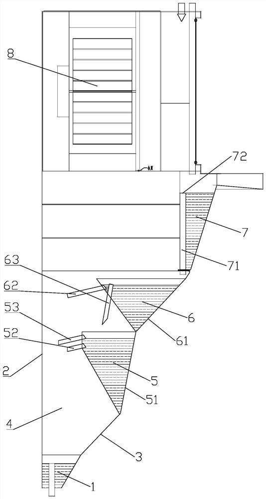
[0025] Figure 1 ~ Figure 3 It schematically shows a power rotary purification device for a smoke and mist collector according to an embodiment of the present invention.

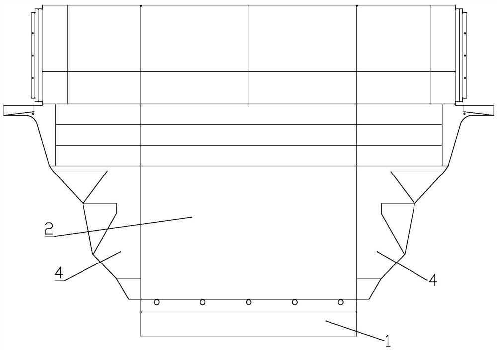
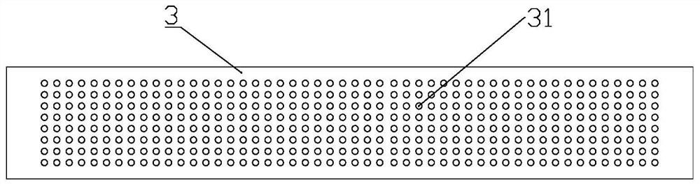
[0026] refer to figure 1 The power rotary purification device of the smoke and demist machine includes an oil collecting tank 1, a rear plate 2, an air inlet orifice plate 3, two side plates 4, a first cooling water tank 5, a second cooling water tank 6, a third cooling water tank 7, Fan 8 and plant fiber purifier 9.

[0027] The two side plates 4 are oppositely arranged and connected to both sides of the rear plate 2 and the air inlet hole plate 3, and the oil collecting tank 1 is fixedly connected to the lower side of the rear plate 2, the air inlet hole plate 3 and the two side plates 4, so as to A lower sealed warehouse body is formed. The inside of the bin body is provided with a first cooling water tank 5, a second cooling water tank 6, a third cooling water tank 7, a fan 8 and a plant fiber purifie...

Embodiment 2

[0038] This embodiment provides a power rotary purification method for a smoke collector and demist machine suitable for the aforementioned power rotary purification device for a smoke collector and demist machine, including the following steps:

[0039] S1. Inject purified water into the third cooling water tank 7 through the water inlet, and flow downstream to the second cooling water tank 6 and the first cooling water tank 5, and then flow into the oil collecting tank 1. The purified water can be tap water or Clean water with deodorant added or other liquids that can be used for purification, etc. Turn on the blower fan 8 so that the gas that needs to be purified outside the warehouse enters the warehouse body from the air inlet 31 of the air inlet hole plate 3 .

[0040] S2. The gas continuously passes through the multiple air inlet holes 31 on the air inlet orifice plate 3 to form a plurality of wind columns, which flow upward obliquely and form a negative pressure above th...


PUM


Abstract

The invention discloses a power rotary purification device for a smoke collecting demister. The power rotary purification device is characterized by comprising an oil collecting water tank, a rear plate, an air inlet pore plate and two side plates, wherein the two side plates are oppositely arranged and connected to the two sides of the rear plate and the air inlet pore plate, the oil collecting water tank is fixedly connected to the rear plate, and the air inlet pore plate and the lower sides of the two side plates form a bin body with the sealed lower portion; a fan is arranged in the bin body, the air inlet hole plate is obliquely arranged, and a plurality of air inlet holes are formed in the air inlet hole plate. The invention further provides a smoke collecting demister power rotary purification method suitable for the power rotary purification device of the smoke collecting demister, when the fan sucks gas and the gas passes through the air inlet hole plate connected with the upper side of the oil collecting water tank, negative pressure can be formed on the upper side of the oil collecting water tank, and water in the oil collecting water tank or water and other liquid for absorbing the purified liquid to upward flow in the air inlet hole plate so as to be rapidly and sufficiently mixed with the gas. A good absorption and purification effect can be achieved through rapidfusion of water and gas, and harmful ingredients and peculiar smells in the gas can be removed.

Description

technical field [0001] The invention relates to the field of purification of polluted gases, in particular to a power rotary purification device and a purification method of a smoke and mist collector. Background technique [0002] In recent years, the impact of air pollution on people's health has become increasingly prominent. Human beings need cleaner air and a clean environment to improve their living standards and health levels. Therefore, the requirements for environmental protection have also been greatly improved. However, at present, various purification devices have the problems of backward technology, high energy consumption, bulky volume and poor purification effect. They cannot quickly purify the polluted gases generated by production and production activities and cannot meet the emission standards after purification. Contents of the invention [0003] Aiming at the above problems, the present invention provides a set of power rotary purification device and p...

Claims


Application Information

Patent Timeline
Patent Type & Authority Applications(China)
IPC IPC(8): B01D53/18
CPCB01D53/18B01D53/1487B01D2257/708B01D2257/702
Inventor 许廷杨许馨予张光祥
Owner 许廷杨
Why Eureka
Try Eureka