
Multifunctional environment-friendly welding mechanism capable of treating welding fumes

A welding mechanism and multi-functional technology, applied in the direction of welding equipment, auxiliary welding equipment, welding/cutting auxiliary equipment, etc., can solve the problems of harmful smoke, affecting the working environment, and generating a large amount, so as to avoid collision damage and save manual operation Effect

Active Publication Date: 2020-11-24
山东超工激光科技有限公司
View PDF7 Cites 1 Cited by
  • Summary
  • Abstract
  • Description
  • Claims
  • Application Information

AI Technical Summary

Problems solved by technology

[0002] Welding, also known as welding and welding, refers to the joining of metals or other thermoplastic materials by means of heating, high temperature or high pressure, and the connection of two or more materials of the same or different kinds into one through bonding and diffusion between atoms or molecules , but there are still some deficiencies in the existing welding mechanism. For example, the existing welding mechanism is generally simple in structure, and requires the staff to fix the object with one hand and weld with the other hand, which affects the efficiency of welding, and a large amount of energy will be generated during the welding process. Harmful smoke, affecting the working environment

Method used


Image

  • Multifunctional environment-friendly welding mechanism capable of treating welding fumes
  • Multifunctional environment-friendly welding mechanism capable of treating welding fumes
  • Multifunctional environment-friendly welding mechanism capable of treating welding fumes

Examples


Embodiment Construction

[0020] The following will clearly and completely describe the technical solutions in the embodiments of the present invention with reference to the accompanying drawings in the embodiments of the present invention. Obviously, the described embodiments are only some, not all, embodiments of the present invention. Based on the embodiments of the present invention, all other embodiments obtained by persons of ordinary skill in the art without making creative efforts belong to the protection scope of the present invention.

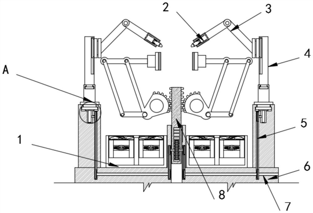
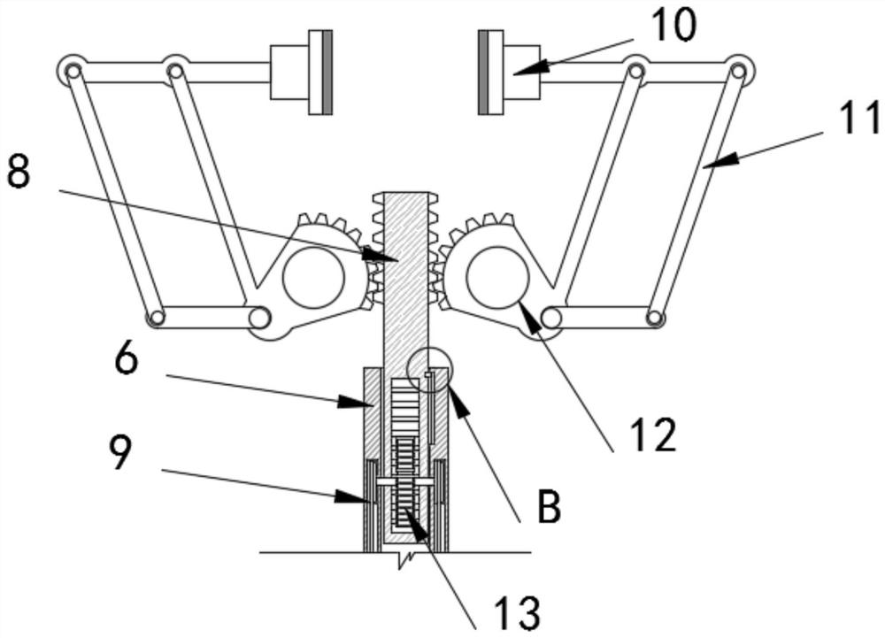
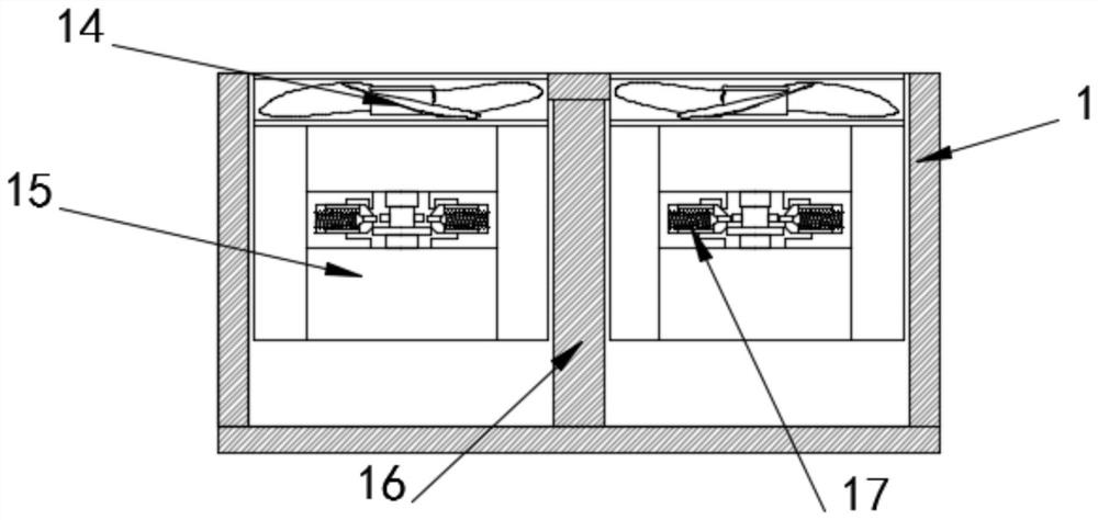
[0021] see Figure 1-6 , a multifunctional environment-friendly welding mechanism capable of processing welding fumes, including a mounting frame 6, an adjusting rod 8 is slidably connected to the middle position of the front surface of the mounting frame 6, and the front surface of the mounting frame 6 is located on the left and right sides of the adjusting rod 8 Both sides are fixedly connected to the processing box 1, the inside of the processing box 1 is f...


PUM


Abstract

The invention provides a multifunctional environment-friendly welding mechanism capable of treating welding fumes. An adjusting rod is in sliding connection to the middle position of the front surfaceof a mounting rack, and the positions, located on the left side and the right side of the adjusting rod, of the front surface of the mounting rack are fixedly connected with treatment boxes. A variable resistor is mounted at the position, located on the right side of the adjusting rod, of the front end in the mounting rack in an embedded manner. Fans are mounted on the left side and the right side of the front surface of each treatment box. Through rotating of a drive shaft, clamping plates are driven to clamp a welding part, manual operation is saved, and welding heads descend while clampingis achieved, so that operation and machining of workers are convenient; after machining is finished, the clamping plates achieve loosening, the welding heads ascend, and the situation that the welding heads are damaged due to colliding is avoided; and when welding fumes are immersed in treatment liquid, the welding fumes and the treatment liquid react to neutralize harmful substances of the welding fumes, then the welding fumes are exhausted by the fans on the outer side, flowing of air surrounding the welding part is increased while the fans on the two sides run, and the welding part is cooled when air flows.

Description

technical field [0001] The invention relates to the field of welding technology, in particular to a multifunctional environment-friendly welding mechanism capable of processing welding smoke. Background technique [0002] Welding, also known as welding and welding, refers to the joining of metals or other thermoplastic materials by means of heating, high temperature or high pressure, and the connection of two or more materials of the same or different kinds into one through bonding and diffusion between atoms or molecules , but there are still some deficiencies in the existing welding mechanism. For example, the existing welding mechanism is generally simple in structure, and requires the staff to fix the object with one hand and weld with the other hand, which affects the efficiency of welding, and a large amount of energy will be generated during the welding process. Harmful fumes affect the working environment. Contents of the invention [0003] In order to solve the a...

Claims


Application Information

Patent Timeline
IPC IPC(8): B23K37/00B23K37/04B23K37/02
CPCB23K37/00B23K37/0443B23K37/02
Inventor 陈影
Owner 山东超工激光科技有限公司
Learn More