Liquid nitrogen conformal inner-cooling forming cutter and mounting method thereof

A technology of cold forming and liquid nitrogen, which is applied to lathe tools, manufacturing tools, accessories of tool holders, etc., can solve the problems of heavy pollution, achieve the effect of reducing work burden, avoiding easy damage of tools, and convenient cooling

Active Publication Date: 2020-11-24
CHENGDU TOOL RES INST
View PDF18 Cites 2 Cited by
  • Summary
  • Abstract
  • Description
  • Claims
  • Application Information

AI Technical Summary

Problems solved by technology

[0005] The present invention intends to provide a liquid nitrogen conformal internal cooling formi

Method used


Image

  • Liquid nitrogen conformal inner-cooling forming cutter and mounting method thereof
  • Liquid nitrogen conformal inner-cooling forming cutter and mounting method thereof
  • Liquid nitrogen conformal inner-cooling forming cutter and mounting method thereof

Examples


Embodiment 1

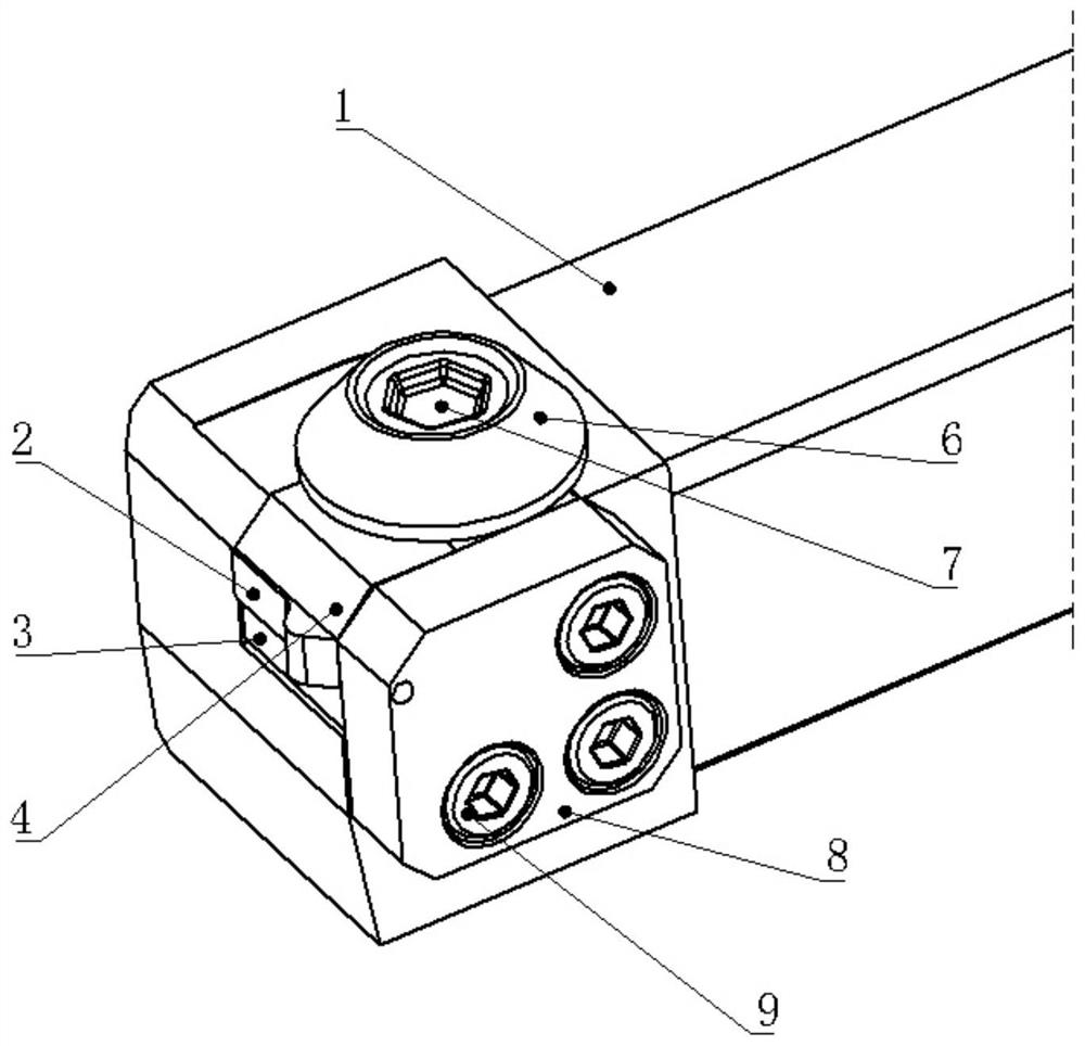
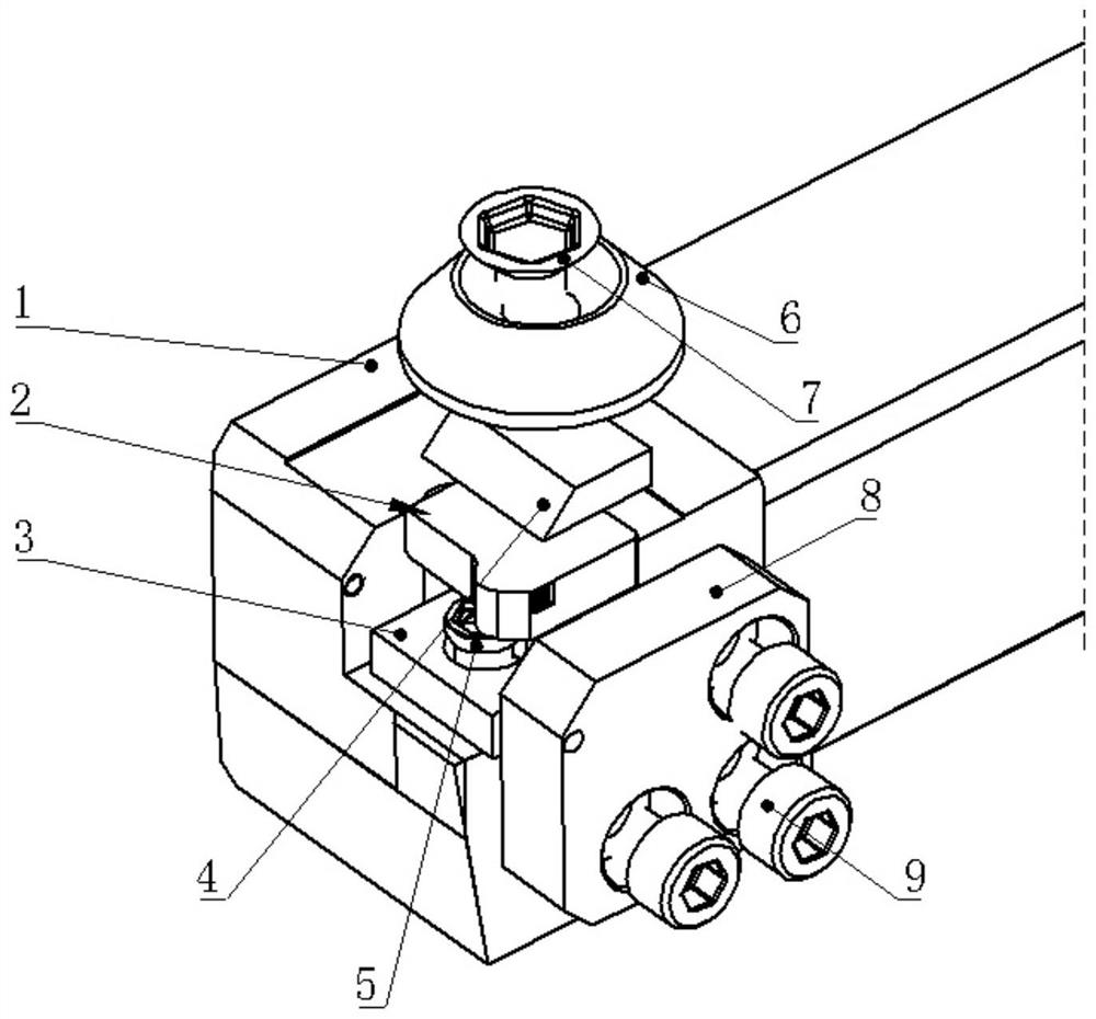
[0044] The embodiment is basically as attached figure 1 and figure 2 As shown: the liquid nitrogen conformal internal cooling forming tool in this embodiment solves the problem that the cutting edge line of the traditional forming tool is long and the external cooling cannot achieve the ideal cooling effect; at the same time, it solves the problem that liquid nitrogen is easy to make each The problem of freezing of functional parts, and the ability to recycle liquid nitrogen.

[0045] The liquid nitrogen conformal internal cooling forming tool in this embodiment includes the following parts:

[0046] A knife body 1 with a liquid nitrogen channel with a heat-insulating layer. In this embodiment, the knife body 1 has a block structure, and the surface of the knife body 1 is evenly coated with a heat-insulating layer. The heat-insulating layer can protect liquid nitrogen from flowing through the knife. The part of the cutter body 1 will not freeze when the cutter body 1 is in ...

Embodiment 2

[0061] The difference from Embodiment 1 is that there are four lateral pressure screws 9 in this embodiment, and the threaded holes corresponding to the four lateral pressure screws 9 are arranged in the shape of a "mouth", wherein the threaded hole in the upper left corner is the same as the The blade 2 limiting hole on the blade 2 is facing, so that all honeycomb holes on the blade 2 can flow out through the threaded hole. The screw located in the threaded hole is an axial hollow structure, that is, the outer side of the screw is provided with external threads, which are used to fix the side pressure plate 8 and the cutter body 1, and the axial channel of the screw communicates with the lower limit hole of the blade 2 for To make the liquid nitrogen passing through the honeycomb hole flow, the screw is called a through screw, and the axial channel of the screw is called the liquid nitrogen channel outlet.

Embodiment 3

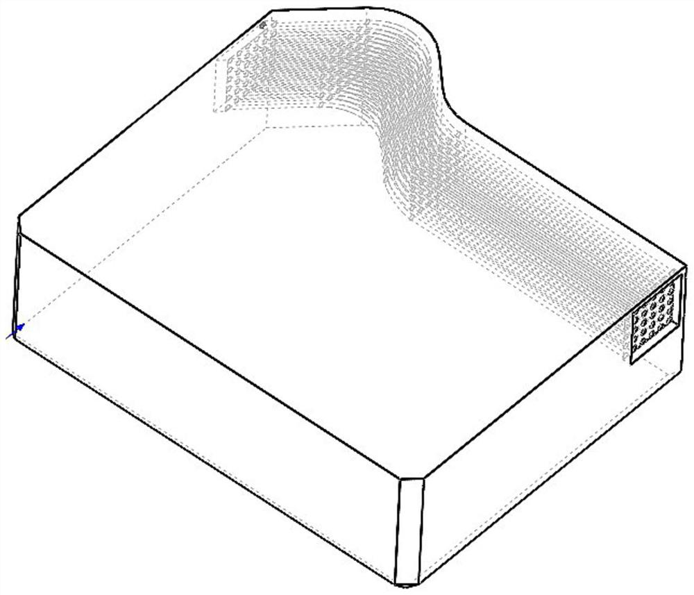
[0063] The difference from Embodiment 1 is that the heat insulation layer in this embodiment is not directly coated on the surface of the cutter body 1, such as Figure 5 As shown, the heat insulation layer in this embodiment is arranged at the end of the cutter body 1 to be in contact with the blade 2. On the position corresponding to the honeycomb hole at the rear end of the blade 2, there is a corresponding heat insulation layer on the heat insulation layer. Layer hole, the heat insulation layer hole runs through the heat insulation layer all the time, so that liquid nitrogen can be introduced into the blade 2 honeycomb holes through the heat insulation layer hole.


PUM


Abstract

The invention relates to the field of cutters, and discloses a liquid nitrogen conformal inner-cooling forming cutter and a mounting method thereof. The liquid nitrogen conformal inner-cooling formingcutter comprises a cutter body, the cutter body is provided with a blade mounting groove, a cutter pad, a blade, a chip breaker and a pressing plate are sequentially mounted in the blade mounting groove from bottom to top, and a liquid nitrogen channel allowing liquid nitrogen to pass is formed in the blade. According to the liquid nitrogen conformal inner-cooling forming cutter and the mountingmethod thereof, the problem that environment pollution is large when an existing cutter is cooled through a cooling medium is effectively solved.

Description

technical field [0001] The invention relates to the field of cutters, in particular to a liquid nitrogen conformal internal cooling forming cutter and an installation method thereof. Background technique [0002] Cooling medium is a common consumable in the use of cutting tools. The existing cooling medium generally adopts cooling liquid, which is divided into inorganic salt type and organic acid type. Regardless of whether it is an inorganic salt type or an organic acid type cooling liquid, it will form after the cooling is completed. [0003] As the requirements for environmental protection are getting higher and higher, all processing machinery manufacturing enterprises are looking for environmentally friendly and clean processing technologies. [0004] At present, the processing using liquid nitrogen as a cooling medium has appeared. However, the traditional forming tool has a long edge line, and the external cooling cannot achieve the ideal cooling effect; liquid nit...

Claims


Application Information

Patent Timeline
IPC IPC(8): B23Q11/10B23B27/10
CPCB23B27/10B23Q11/10
Inventor 李代刚陈云王林曾莉梅译丹
Owner CHENGDU TOOL RES INST
Why Eureka
Try Eureka