
Polishing device for mechanical part machining

A technology of mechanical parts and components, which is applied in the direction of grinding drive device, grinding machine tool parts, grinding/polishing safety device, etc., which can solve the problem of damaging the grinding device, increasing the error of plate-shaped mechanical parts, and difficult adjustment of the grinding device and other problems, to achieve the effect of reducing grinding error, reducing noise, and easy to use

Inactive Publication Date: 2020-11-24
卫浩
View PDF10 Cites 2 Cited by
  • Summary
  • Abstract
  • Description
  • Claims
  • Application Information

AI Technical Summary

Problems solved by technology

[0003] Grinding is a kind of surface modification technology. In mechanical production, after the casting of mechanical parts, the surface generally needs to be polished to remove burrs, etc., so that the mechanical parts can be better installed and used. The burrs are usually left when the plate-shaped mechanical parts are formed. During the finishing process, the burrs need to be removed by a grinding device. The existing grinding device has a relatively large vibration during operation. When the vibration is large, it will generate a lot of noise, which will seriously affect the Working environment; in addition, the grinding device is unstable during work, and it is difficult to adjust the grinding device quickly and effectively, which increases the error in the processing of plate-shaped mechanical parts, which not only damages the grinding device, but also makes the polished plate-shaped mechanical parts If it is unqualified, it will seriously affect the product quality, and a lot of smoke and dust will be generated during the grinding process, which will seriously endanger the health of workers under long-term working conditions. In view of the above problems, we propose a grinding device for mechanical parts processing

Method used


Image

  • Polishing device for mechanical part machining
  • Polishing device for mechanical part machining
  • Polishing device for mechanical part machining

Examples


Embodiment Construction

[0027] The technical solutions in the embodiments of the present invention will be clearly and completely described below in conjunction with the accompanying drawings in the embodiments of the present invention. Obviously, the described embodiments are only some of the embodiments of the present invention, not all of them. Based on The embodiments of the present invention and all other embodiments obtained by persons of ordinary skill in the art without making creative efforts belong to the protection scope of the present invention.

[0028] In the description of the present invention, it should be noted that the terms "top", "bottom", "one side", "another side", "front", "rear", "middle part", "inner", " The orientation or positional relationship indicated by "top", "bottom", etc. is based on the orientation or positional relationship shown in the drawings, which is only for the convenience of describing the present invention and simplifying the description, rather than indic...


PUM


Abstract

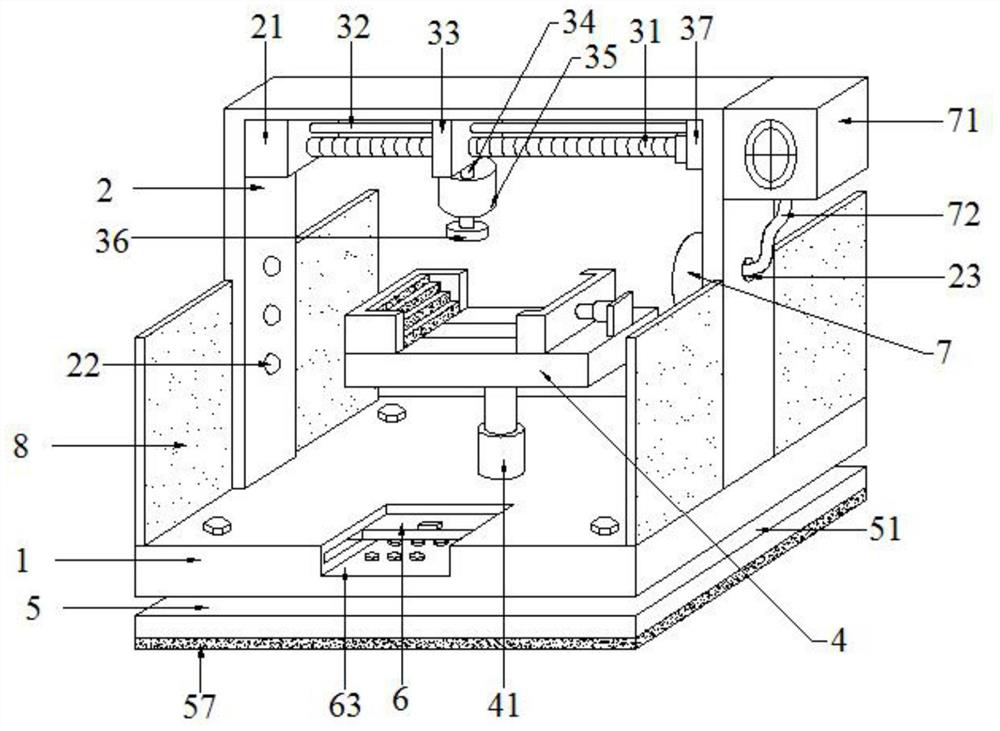
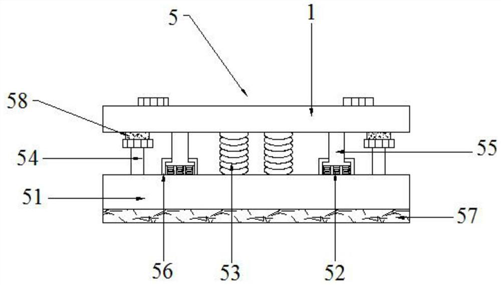
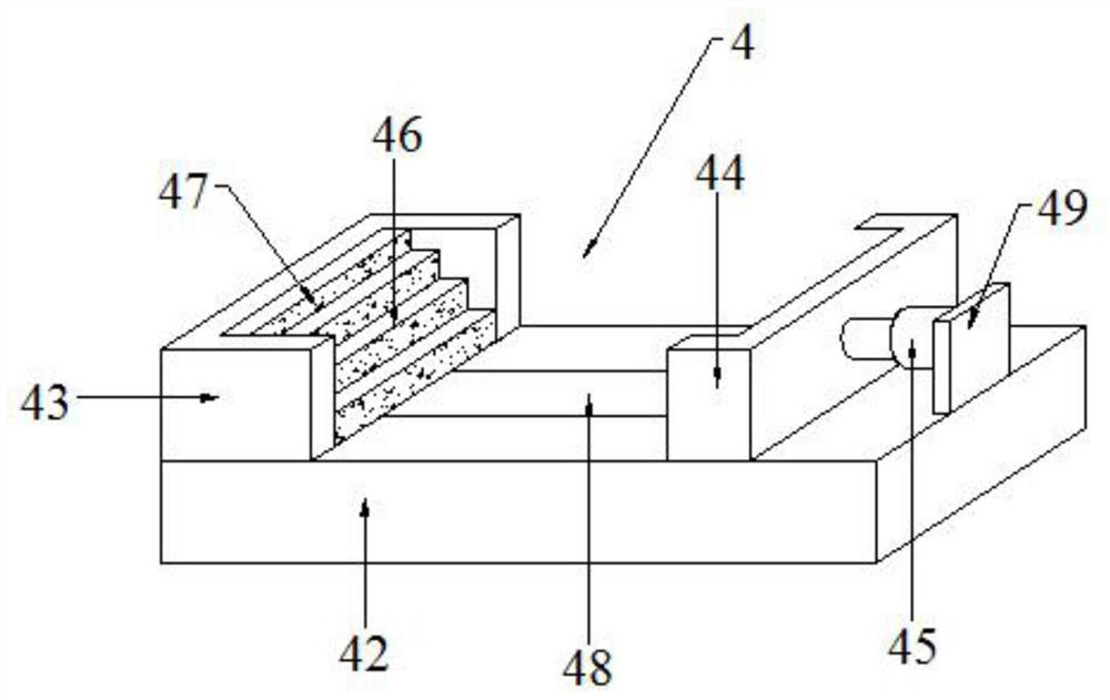
The invention relates to a polishing device for mechanical part machining. The polishing device for mechanical part machining comprises a base plate, U-shaped fixed plates, a servo motor, a fixing assembly and a shock absorbing assembly. The U-shaped fixed plates are welded and fixed to two sides of the upper surface of the base plate, the output end of the servo motor is welded and fixed to rotating bases on the U-shaped fixed plates, a polishing head is connected and fixed to the output end of the polishing motor in a clamping manner, the fixing assembly is arranged at the bottom end of thepolishing head on the upper surface of the base plate, and an operating assembly is arranged on the side of the fixing assembly on the base plate. The polishing device has the beneficial effects thatthe servo motor drives a movable block on a threaded rod to move on a fixed bar to drive the polishing head to adjust, so that the polishing device is smooth to polish and convenient to operate; a platy mechanical part is stably and safely by means of the fixing block and the U-shaped movable block under a second electrical push rod, so that the polishing device is safe to operate; and a first shock absorbing spring buffers vibration on the shock absorbing base, so that noises are reduced and the environment is protected.

Description

technical field [0001] The invention relates to the technical field related to machinery, in particular to a grinding device for processing mechanical parts. Background technique [0002] Machinery refers to the general term for machines and mechanisms. Machinery is a tool device that can help people reduce the difficulty of work or save labor. Items such as chopsticks, brooms, and tweezers can all be called machines, and they are simple machines. A complex machine is composed of two or more simple machines; these more complex machines are usually called machines. [0003] Grinding is a kind of surface modification technology. In mechanical production, after the casting of mechanical parts, the surface generally needs to be polished to remove burrs, etc., so that the mechanical parts can be better installed and used. The burrs are usually left when the plate-shaped mechanical parts are formed. During the finishing process, the burrs need to be removed by a grinding device....

Claims


Application Information

Patent Timeline
Patent Type & Authority Applications(China)
IPC IPC(8): B24B19/00B24B41/04B24B41/06B24B47/22B24B55/06B24B55/12
CPCB24B19/00B24B41/04B24B41/06B24B47/22B24B55/06B24B55/12
Inventor 卫浩
Owner 卫浩
Learn More