
Efficient polishing machine provided with multiple stations

A polishing machine and multi-station technology, applied in surface polishing machine tools, machine tools suitable for grinding the edge of workpieces, grinding/polishing equipment, etc., can solve the problems of insufficient hardware efficiency and affecting the production and processing efficiency of hardware, etc. , to improve the production and processing efficiency, prevent the internal temperature from being too high, and shorten the service life

Pending Publication Date: 2020-11-24
陈显青
View PDF0 Cites 0 Cited by
  • Summary
  • Abstract
  • Description
  • Claims
  • Application Information

AI Technical Summary

Problems solved by technology

[0003] In the existing polishing machine, there is only one set of workpiece clamps to clamp and fix the hardware, and to polish the hardware with abrasive particles, which makes the efficiency of equipment processing hardware obviously insufficient. Although some polishing machines add The way of multiple sets of workpiece fixtures improves the efficiency of hardware processing to a certain extent, but the equipment still needs to stop working before the hardware can be loaded and unloaded, which seriously affects the production and processing efficiency of hardware

Method used


Image

  • Efficient polishing machine provided with multiple stations
  • Efficient polishing machine provided with multiple stations
  • Efficient polishing machine provided with multiple stations

Examples


Embodiment 1

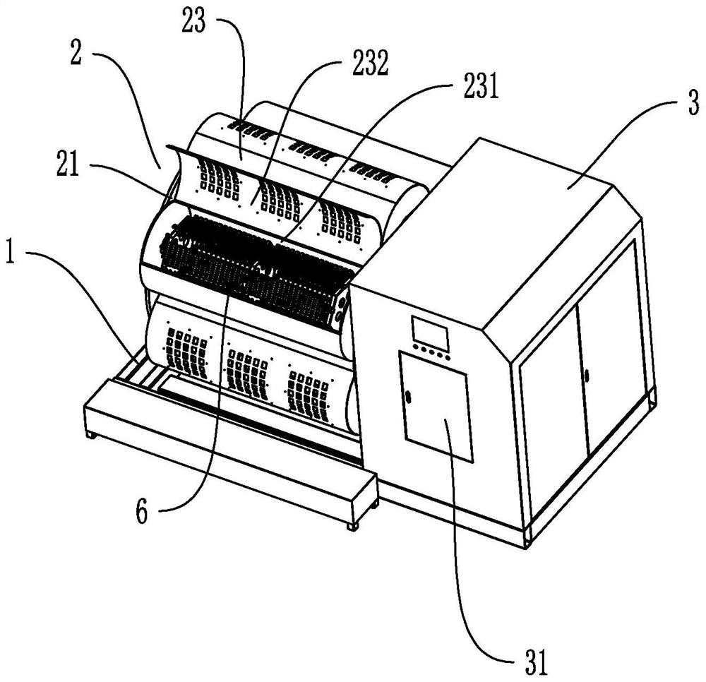
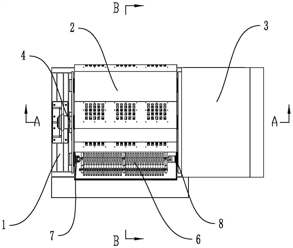
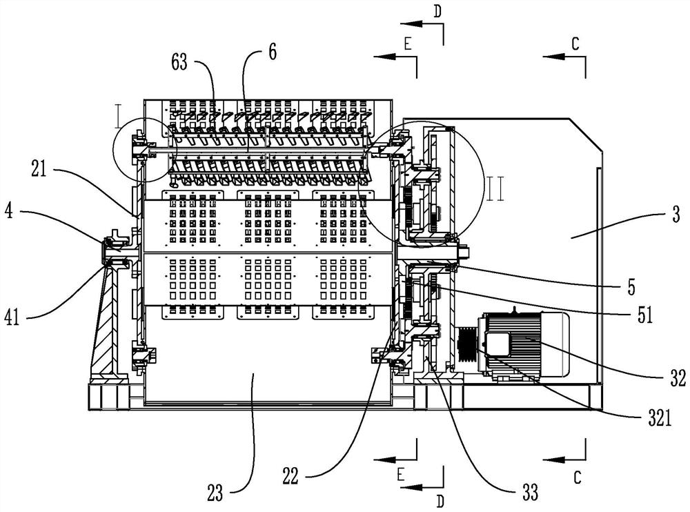
[0045] Embodiment 1, this embodiment discloses a high-efficiency polishing machine with multiple stations, such as Figures 1 to 5 As shown, it includes a frame 1 and a polishing mechanism 2 and a control cabinet 3 positioned on the left and right sides of the frame 1, and the two ends of the polishing mechanism 2 are respectively connected to the frame 1 and the The control cabinets 3 are movably connected to each other, and the polishing mechanism 2 includes a first turntable 21 and a second turntable 22 that are compatible, and a plurality of horizontally arranged polishing rollers 23 are fixedly connected between the first turntable 21 and the second turntable 22, and the polishing rollers 23 The number is set to six groups, and the polishing cylinder 23 includes a fixed cylinder 231 and a movable cover 232 that are detachably connected to each other and a workpiece hanger 6 that is located in the fixed cylinder 231. One end of the fixed cylinder 231 is hingedly connected w...

Embodiment 2

[0052] Embodiment two, this embodiment is on the basis of embodiment one, such as Figures 10 to 12 As shown, a limiting structure 36 compatible with the second turntable 22 is provided on one side of the transmission fixing frame 33, and the limiting structure 36 includes a limiting cylinder 361 and a piston rod fixedly connected with the limiting cylinder 361 The limit rod 362, the second turntable 22 is provided with a limit protrusion 363 that is compatible with the polishing cylinder 23, and the limit protrusion 363 is provided with a limit groove that is compatible with the limit rod 362 , the limiting bosses are evenly distributed around the edge of the second turntable 22 in a circumferential shape, and the outer side of the limiting protrusion 363 is also provided with a reinforcing protrusion integral with it, and the reinforcing protrusion can improve the mechanical strength of the limiting protrusion 363, Prolong its service life; After the limit structure 36 guara...

Embodiment 3

[0054] Embodiment three, this embodiment is on the basis of embodiment two, such as Figure 13 and 14 As shown, the ventilation cavity 9 is formed between the first rotating disk 21, the second rotating disk 22 and a plurality of the fixed cylinders 231, the number of the fixed cylinders 231 is set to six groups, and the second rotating disk 22 and the second The connecting structure 5 is provided with interconnected ventilation slots 221 and ventilation through holes 52, the ventilation through holes 52 are also connected to the control cabinet 3, and the ventilation through holes 52 are also provided with a ventilation gland 53 with a vent. , the control cabinet 3 is provided with a heat dissipation fan 37 suitable for the vent, and a plurality of heat dissipation parts are arranged on the fixed cylinder 231 and the movable cover 232, and the heat dissipation parts cooperate with the ventilation cavity 9. The cover is provided with a metal filter screen fixedly connected to...


PUM


Abstract

The invention discloses an efficient polishing machine provided with multiple stations. According to key points of the technical scheme, the efficient polishing machine comprises a rack, a polishing mechanism and a control cabinet, wherein the polishing mechanism and the control cabinet are located on the left side and the right side of the rack. The two ends of the polishing mechanism are movablyconnected with the rack and the control cabinet correspondingly through a first connecting structure and a second connecting structure. The polishing mechanism comprises a first rotating disc and a second rotating disc. Polishing rollers are fixedly connected between the first rotating disc and the second rotating disc. Each polishing roller comprises a fixing cylinder, a moving cover and a workpiece hanging device. An electronic control cabinet, a main motor, a transmission assembly and a position change motor are arranged in the control cabinet. The main motor is mutually and movably connected with a fourth connecting structure through the transmission assembly. The transmission assembly comprises a transmission fixing frame and a plurality of transmission structures. The number of thetransmission structures is one set less than the number of the rollers. The position change motor is mutually and movably connected with the second connecting structure. The efficient polishing machine has the effects that the structure is simple, the machine does not need to be shut down in the feeding and discharging processes, the production machining efficiency is high, and the product polishing effect is good.

Description

technical field [0001] The invention relates to the technical field of hardware processing equipment, in particular to a high-efficiency polishing machine with multiple stations. Background technique [0002] The polishing machine is specially designed for the surface treatment of steel, aluminum, copper and other hardware. It can quickly repair deep scratches and slight scratches, quickly grind and polish; welding seams, nozzle marks, traces of oxide film, stains and paints It is suitable for deburring, forming rounded corners, and decorative metal processing. It will not form shadows, transition zones, and uneven decorative surfaces during processing. It is an important equipment for metal product production lines. There are many types of hardware, such as door handles, faucets, connecting nuts and other products that are formed by metal processing. There are two symmetrical installation holes on the door handle. [0003] In the existing polishing machine, there is only o...

Claims


Application Information

Patent Timeline
IPC IPC(8): B24B31/02B24B31/12
CPCB24B31/0224B24B31/12
Inventor 陈显青陈爽陈茫林兴豹
Owner 陈显青
Learn More