Board slitting equipment

A kind of equipment and strip cutting technology, which is applied in the direction of wood processing equipment, special forming/shaping machines, manufacturing tools, etc., can solve the problem of reduced template cutting efficiency and achieve the effect of easy cutting

Active Publication Date: 2020-11-24
临沂临港国有资产运营集团有限公司
View PDF6 Cites 9 Cited by
  • Summary
  • Abstract
  • Description
  • Claims
  • Application Information

AI Technical Summary

Problems solved by technology

In this equipment, in the process of cutting the wooden board, the worker needs to manually push the wooden board so that the wooden board is located at the position of the cutting sheet assembly, and in the process of cutting, the worker needs to manually fix the wooden board, thereby reducing the efficiency of template cutting

Method used


Image

  • Board slitting equipment
  • Board slitting equipment
  • Board slitting equipment

Examples


Embodiment 1

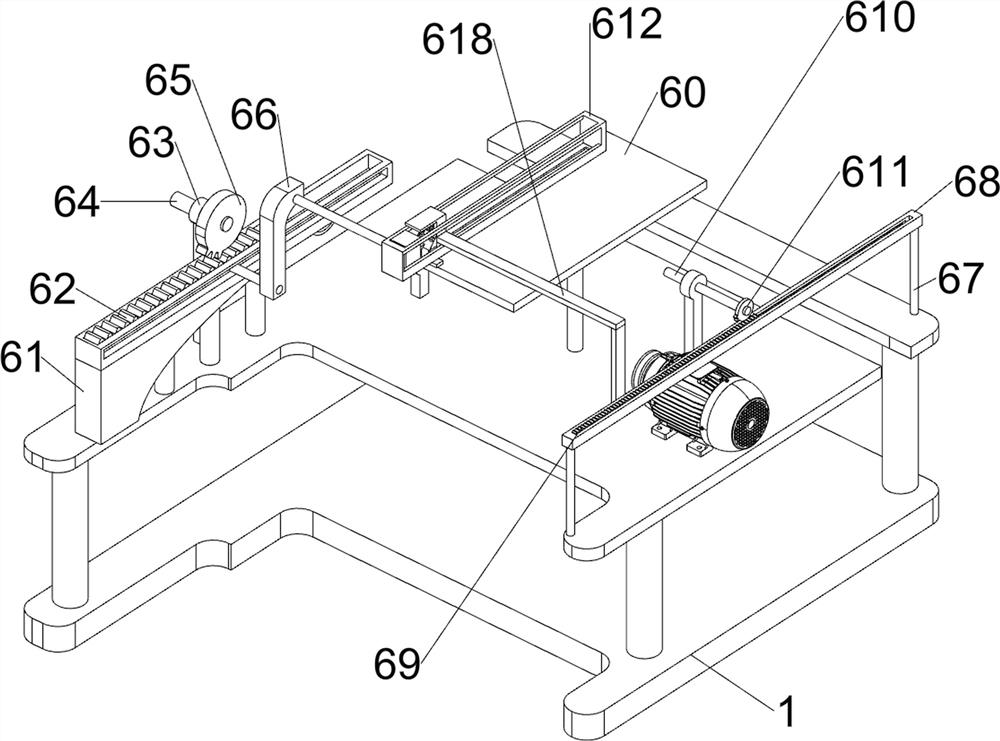
[0024] A kind of plank cutting equipment, such as figure 1 As shown, it includes a base 1, a servo motor 2, a first bearing seat 3, a first rotating shaft 4, a cutting mechanism 5, a propulsion mechanism 6, a first transmission assembly 7, a second transmission assembly 8, a clamping mechanism 9 and a third The transmission assembly 10 is provided with a servo motor 2 in the middle of the upper right side of the base 1, a first bearing seat 3 is provided in the middle of the upper front side of the base 1, a first rotating shaft 4 is connected to the output shaft of the servo motor 2, and a rear side of the upper part of the base 1 is provided. Cutting mechanism 5 is arranged, base 1 top is provided with propulsion mechanism 6, the first transmission assembly 7 is connected with the parts of propulsion mechanism 6 on the left side of first rotating shaft 4, and the second transmission assembly 7 is connected with the parts of propulsion mechanism 6 on the right side of first ro...

Embodiment 2

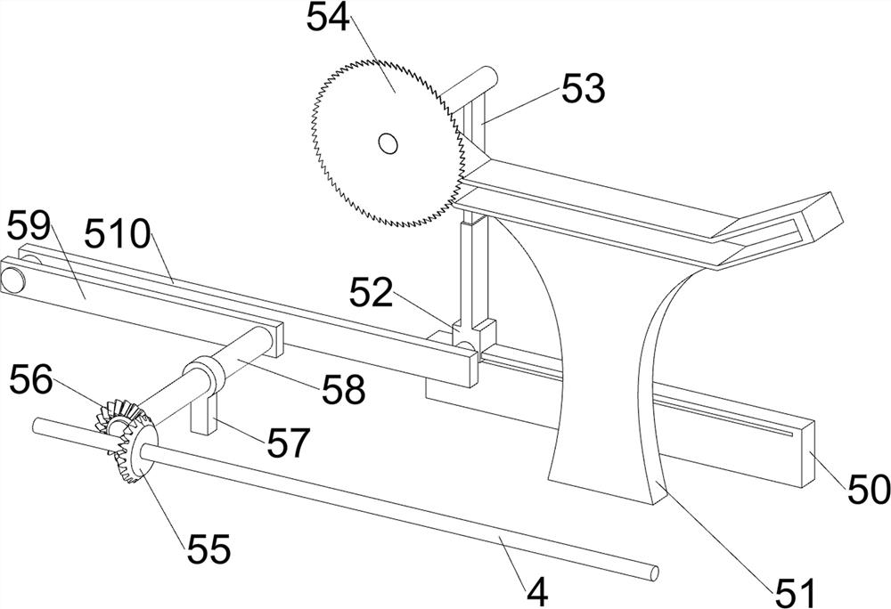
[0027] On the basis of Example 1, such as figure 2 , image 3 , Figure 4 , Figure 5 with Image 6 As shown, the cutting mechanism 5 includes a first slide rail 50, a second slide rail 51, a first slide block 52, a first L-shaped bar 53, an electric saw blade 54, a first bevel gear 55, a second bevel gear 56, The second bearing seat 57, the second rotating shaft 58, the crank 59 and the first connecting rod 510, the base 1 top rear side is provided with the first slide rail 50, the base 1 top rear side is provided with the second slide rail 51, the first slide rail The sliding type in 50 is provided with the first slide block 52, and the sliding type on the first slide block 52 top is provided with the first L-shaped bar 53, and the first L-shaped bar 53 is provided with the electric saw blade 54, and the electric saw blade 54 and the second The slide rail 51 is slidingly connected, the first rotating shaft 4 is provided with a first bevel gear 55, the base 1 top left re...

Embodiment 3

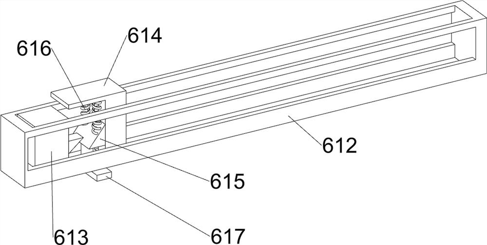
[0034] On the basis of Example 2, such as Figure 7 As shown, it also includes the seventh slide rail 11, the third rack 12, the third spring 13, the fourth missing gear 14, the limit plate 15, the push plate 16 and the connecting plate 17 for pressing down, and the right side of the base 1 top is provided with The seventh slide rail 11 is arranged, and the third rack 12 is slidingly provided in the seventh slide rail 11, the seventh slide rail 11 is connected with the third rack 12 with a third spring 13, and the first rotating rod 610 is provided with a third rack 12. Four missing gears 14, the fourth missing gear 14 meshes with the third rack 12, the right part of the third rack 12 is provided with a connecting plate 17, the upper part of the connecting plate 17 is slidingly provided with a push plate 16 for pressing down, and the second slide rail 51 The front portion is provided with a limiting plate 15, and the limiting plate 15 is slidably connected with the push plate ...


PUM


Abstract

The invention relates to slitting equipment, in particular to board cutting equipment, and provides is the board slitting equipment which can fix a board and can automatically push the board for slitting. The board slitting equipment comprises a base, a servo motor, a first bearing block and a first rotating shaft, wherein the base is used for installing the entire equipment; the servo motor is arranged at one side of the upper part of the base; the first bearing block is arranged at the side, close to the servo motor, of the upper part of the base; and the first rotating shaft is arranged onan output shaft of the servo motor. The board cutting equipment achieves the effect of fixing the board and automatically pushing the board for slitting; the board which needs to be slit is put on a fixing table, and a first rack and a second rack move backwards, and accordingly, a special-shaped block and a fixed block are driven to move backward, and then, the board can be pushed backward by a pushing block.

Description

technical field [0001] The invention relates to a strip cutting equipment, in particular to a wood strip cutting equipment. Background technique [0002] Wood is an important raw material, which is widely used in various fields such as construction and home decoration. Wood processing is an important process. In the field of furniture manufacturing and processing, people often cut wood boards into wooden slats to facilitate subsequent processing and use. Therefore, wood board cutting devices are used more and more frequently in board processing. [0003] Existing plank cutting equipment, such as the Chinese patent No. CN204935808U, discloses a plank cutting machine, which includes a frame and stop rods arranged on both sides of the frame, and the frame includes a feed end and the discharge end, the frame is provided with a cutting blade assembly, and the end of the limit rod opposite to the feed end is a slope inclined towards the direction of the other limit rod. In this ...

Claims


Application Information

Patent Timeline
Patent Type & Authority Applications(China)
IPC IPC(8): B27C5/02B27C5/06
CPCB27C5/02B27C5/06
Inventor 范书华
Owner 临沂临港国有资产运营集团有限公司
Why Eureka
Try Eureka