Large fold-to-span ratio solar wing

A solar wing and folding aspect ratio technology, which is applied in the field of large folding aspect ratio solar wings, can solve the problems that it is difficult to meet the special application requirements of light and small satellite platforms, the solar wing deployment mechanism is complex, and the mass is heavy, and the product is light in weight and structure. Simple and highly reliable mechanism

Active Publication Date: 2022-03-11
HARBIN INST OF TECH
View PDF0 Cites 0 Cited by
  • Summary
  • Abstract
  • Description
  • Claims
  • Application Information

AI Technical Summary

Problems solved by technology

[0003] At present, the solar wing deployment devices that are widely used are mainly hinged expandable mechanisms and rod-shaped expandable mechanisms. With the continuous development of technology, miniaturized and lightweight satellite platforms are the trend of future development. The traditional solar wing deployment mechanism is complex, heavy and large in size, which is difficult to meet the special application requirements of light and small satellite platforms.

Method used


Image

  • Large fold-to-span ratio solar wing
  • Large fold-to-span ratio solar wing
  • Large fold-to-span ratio solar wing

Examples


Embodiment 1

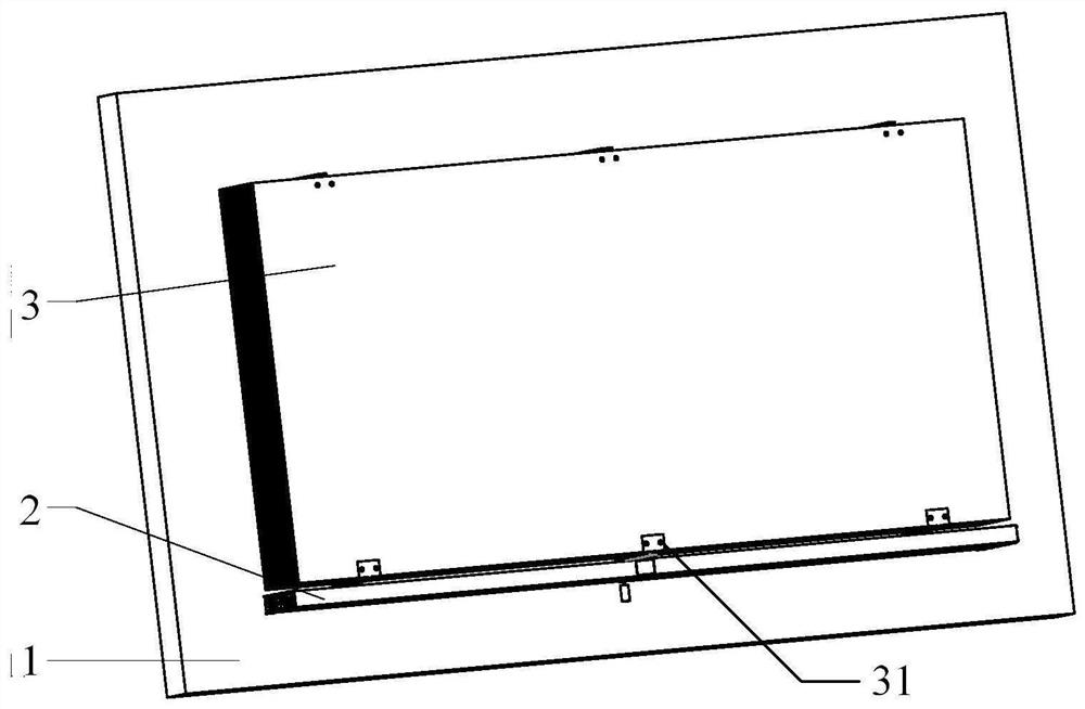
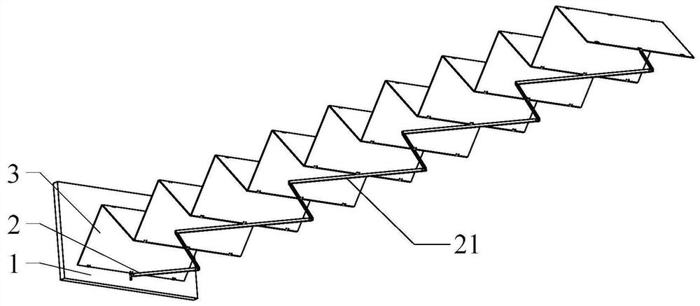
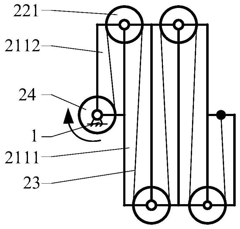
[0039]The large folding-to-span ratio solar wing provided by the present invention includes a deployment mechanism 2 and a solar cell substrate assembly 3 arranged on a satellite body 1; the deployment mechanism 2 includes a deployment rod assembly 21, a guide roller assembly 22 and a driving rope 23; The deployment rod assembly 21 includes a plurality of deployment rods 211 and a first hinge 212 connecting the deployment rods 211 to form an open-loop chain structure. The deployment rod assembly 21 can be folded and unfolded. The sides of the adjacent deployment rods 211 abut against each other, and in the unfolded state, the ends of the adjacent deployment rods 211 abut against each other; the guide roller assembly 22 includes a guide roller 221 located at the joint of the deployment rod 211 and coaxial with the hinge; One end of the rod assembly 21 is hinged to the satellite body 1 through a second hinge 213, and a reel 24 coaxial with the second hinge 213 is provided at the ...

Embodiment 2

[0047] The difference from Embodiment 1 is that the solar cell substrate assembly 3 is composed of a plurality of rigid substrates, and the rigid substrates are hinged by at least one third hinge 31, and the two ends of the solar cell substrate assembly 3 are connected to the unfolded Both ends of the rod assembly 21 are hinged, and the middle parts of the even-numbered seams of all rigid substrates are hinged with the middle parts of the expansion rod 211 .

[0048] The length of the rigid base is half the length of the long deployment rod 2111.

[0049] The advantage of this embodiment is that the shape of the rigid substrate is determined when it is folded and unfolded. Compared with the flexible substrate, space needs to be reserved to prevent rigid bending, and the folded state of the rigid substrate takes up less space. When the length of the rigid substrate is half of the length of the long deployment rod 2111, the backlight surface of the solar cell substrate assembly ...


PUM


Abstract

The present invention provides a solar wing with a large folding-to-span ratio, including an unfolding mechanism and a solar cell substrate assembly arranged on a satellite body; the unfolding mechanism includes an unfolding rod assembly, a guide roller assembly and a driving rope; The deployment rod and the first hinge connecting the deployment rods to form an open-loop chain structure, the deployment rod assembly can be folded and unfolded, wherein, in the folded state, the sides of adjacent deployment rods are against each other, and in the unfolded state, The ends of the adjacent deployment rods are against each other; the guide roller assembly includes a guide roller arranged at the joint of the deployment rod and coaxial with the first hinge. In the present invention, the solar wing with large folding ratio is deployed by rope drive, with fewer parts and components, simple structure, small space occupation, light product weight and high mechanism reliability; according to different task requirements, it can be increased or decreased The number of deployment rods and rollers enables the deployment of solar cell substrates of different lengths without redesigning the structure.

Description

technical field [0001] The invention relates to the technical field of aerospace equipment, in particular to a solar wing with a large folding-to-span ratio. Background technique [0002] The solar wing is the medium that collects sunlight and converts it into electrical energy. It is the energy source for the movement of the spacecraft and is one of the most important components of the spacecraft. It has certain functions of deployment and structural support. There are solar cells matched with it. When the spacecraft is launched, the deployment device and the solar cells are in a folded and compressed state to reduce airflow resistance. According to the deployment requirements, after the satellite and arrow are separated or enter orbit, the deployment device is deployed. And constantly adjust the angle during the satellite flight to adapt to the direction of sunlight. [0003] At present, the solar wing deployment devices that are widely used are mainly hinged expandable m...

Claims


Application Information

Patent Timeline
Patent Type & Authority Patents(China)
IPC IPC(8): B64G1/44B64G1/22B64G1/10
CPCB64G1/44B64G1/222B64G1/10
Inventor 杨飞岳洪浩马超王宇
Owner HARBIN INST OF TECH
Why Eureka
Try Eureka