Aeration device for sewage treatment

A technology of aeration device and sewage treatment, which is applied in oxidation water/sewage treatment, water/sludge/sewage treatment, water treatment parameter control, etc. Liquid mixing and other problems, to achieve uniform distribution of aeration holes, increase work efficiency, and increase the effect of uniformity

Pending Publication Date: 2020-11-24
铜陵六国威立雅水务有限责任公司
View PDF1 Cites 0 Cited by
  • Summary
  • Abstract
  • Description
  • Claims
  • Application Information

AI Technical Summary

Problems solved by technology

[0003] Chinese patent discloses a kind of aeration used for sewage treatment, (authorized announcement number CN109231426A), this patented technology can control the department to judge whether the aeration blank area needs local oxygenation according to the information received and control the aeration point to adjust to Corresponding working conditions, so as to realize the balanced aeration of various areas of sewage. However, most of the aeration devices currently on the market for sewage treatment have small aeration circumference and low aeration uniformity, which is not conducive to the treatment efficiency of sewage. Most of them cannot control the aeration volume of aeration, which is not conducive to aeration efficiency, resulting in low work efficiency, and cannot achieve the effect of water-liquid mixing. Most of them do not have auxiliary stirring devices, which cannot make the aeration bubbles evenly distributed in the water liquid
Solve the problem of small aeration circumference and solve the problem of no auxiliary stirring device

Method used


Image

  • Aeration device for sewage treatment
  • Aeration device for sewage treatment
  • Aeration device for sewage treatment

Examples


Embodiment Construction

[0025] The following will clearly and completely describe the technical solutions in the embodiments of the present invention with reference to the accompanying drawings in the embodiments of the present invention. Obviously, the described embodiments are only some, not all, embodiments of the present invention. Based on the embodiments of the present invention, all other embodiments obtained by persons of ordinary skill in the art without making creative efforts belong to the protection scope of the present invention.

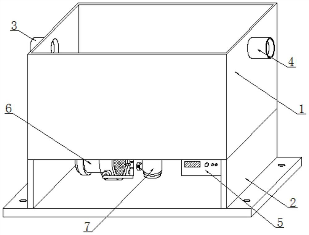
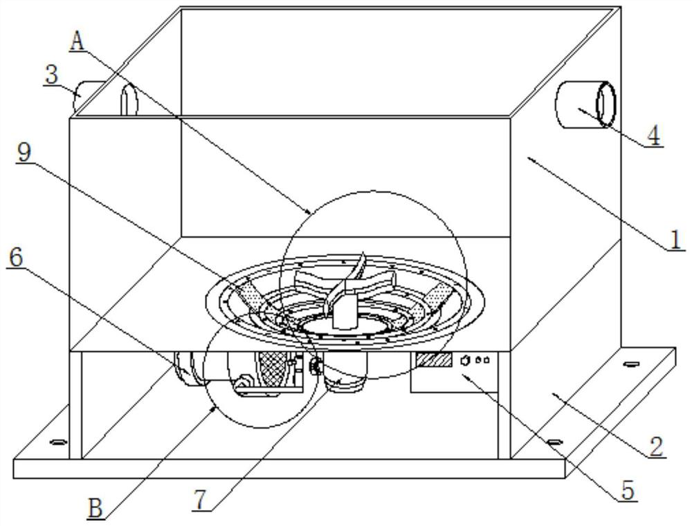
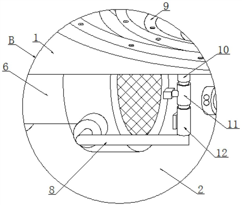
[0026] see Figure 1~6 , in an embodiment of the present invention, an aeration device for sewage treatment, comprising an aeration tank 1, the outer surface of the upper end of one side of the aeration tank 1 is welded with a water inlet 3, and the outer surface of the upper end of the other side of the aeration tank 1 is The water outlet 4 is welded through the surface, the support seat 2 is welded on the lower surface of the aeration tank 1, the control box...


PUM


Abstract

The invention discloses an aeration device for sewage treatment and particularly relates to the technical field of sewage treatment aeration devices. The aeration device comprises an aeration tank, wherein a water inlet is soldered in the outer surface at the upper end of one side of the aeration tank in a running through manner, and a water outlet is soldered in the outer surface at the upper endof the other side of the aeration tank in a running through manner; a supporting seat is soldered on the lower surface of the aeration tank; a control tank is soldered on one side of the lower surface of the aeration tank; an aeration component is arranged on the lower surface inside the aeration tank; an aeration fan is arranged on one side of the upper surface of the supporting seat; a motor isarranged on the lower surface of the aeration tank; a gas delivery pipe is arranged on the front surface of the aeration fan in a running through manner; an airflow sensor is arranged at the upper end of the gas delivery pipe; and a battery valve is arranged at the upper end, close to the position of the airflow sensor, of the gas delivery pipe. The aeration device for sewage treatment has a large aeration range, can control the volume of the aeration rate of aeration and is provided with an assistant agitation device.

Description

technical field [0001] The invention relates to the technical field of sewage treatment aeration devices, in particular to an aeration device for sewage treatment. Background technique [0002] Sewage treatment is the process of purifying sewage to meet the water quality requirements of being discharged into a certain water body or reused. Sewage treatment is widely used in construction, agriculture, transportation, energy, petrochemical, environmental protection, urban landscape, medical treatment, catering, etc. field, and more and more people have entered into the daily life of ordinary people. Aeration refers to artificially injecting air into the biochemical aeration tank through appropriate equipment to achieve the expected purpose. Aeration not only makes the liquid in the tank contact with air to fill Oxygen, and due to the agitation of the liquid, the transfer of oxygen in the air to the liquid is accelerated, thereby completing the purpose of oxygenation. Sewage tr...

Claims


Application Information

Patent Timeline
IPC IPC(8): C02F1/74B01F7/16
CPCC02F1/74C02F2209/38B01F27/808B01F2101/305
Inventor 李世民周瑜杨兆涛
Owner 铜陵六国威立雅水务有限责任公司
Why Eureka
Try Eureka